
White LED Flood Lamp circuit

The white LED light circuit is designed to provide efficient illumination while minimizing energy usage. The primary component is a white LED, which operates at a forward voltage typically ranging from 2.8V to 3.6V, depending on the specific LED used. This LED is connected in series with a current-limiting resistor to ensure that it operates within its safe current rating, usually around 20 mA for standard LEDs.
The energy-saving aspect of the design can be attributed to the use of a low-power LED, which converts a higher percentage of electrical energy into light rather than heat, in contrast to traditional incandescent bulbs. The circuit can be powered by a standard DC power supply or battery, making it versatile for various applications.
For outdoor use, the circuit may also include a waterproof housing to protect the LED from environmental factors. Additionally, if the design is intended for automatic operation, a light sensor or a timer circuit can be integrated to control the LED based on ambient light levels or time of day.
Overall, this simple LED circuit is an effective solution for porch lighting, combining functionality with energy efficiency.This White LED lights illuminates your porch with cool white light. The circuit is too simple and energy saving design. Its current consumption is practica. 🔗 External reference
Related Circuits
Most peripherals that interface with a PC utilize a USB port. The computer's power supply circuit, specifically the switched-mode power supply (SMPS), is designed to provide constant power to all internal components. However, when external peripherals that require a...

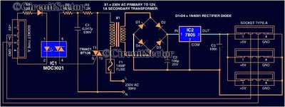
The adjustable power supply can be reconfigured by changing the value of V2 and enhancing other components as needed. The output voltage is calculated using the formula Vnm = 1.25 (1 + R2/R^). Additionally, R2 can be modified as...
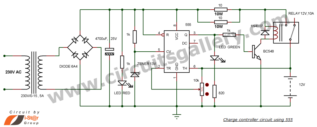
This is a simple DIY charge controller schematic created in response to a request from one of the readers on our Facebook page. The primary component of this automatic battery charger circuit is a 555 timer, which compares the...
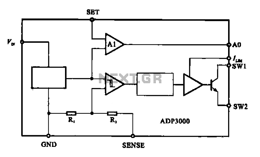
The ADP3000 is an integrated circuit featuring a block diagram that illustrates its internal structure as a high-frequency switching regulator. The ADP3000 integrated circuit is designed to provide efficient power management in various applications, particularly in systems requiring high-frequency switching...
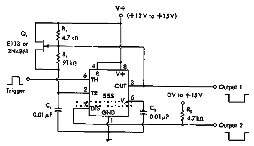
The timer 555 is activated by a positive trigger pulse, which results in negative output pulses. In scenarios where the duty cycle exceeds 99%, heavy loads can be disconnected from pin 7 without impacting timing accuracy, although loads exceeding...
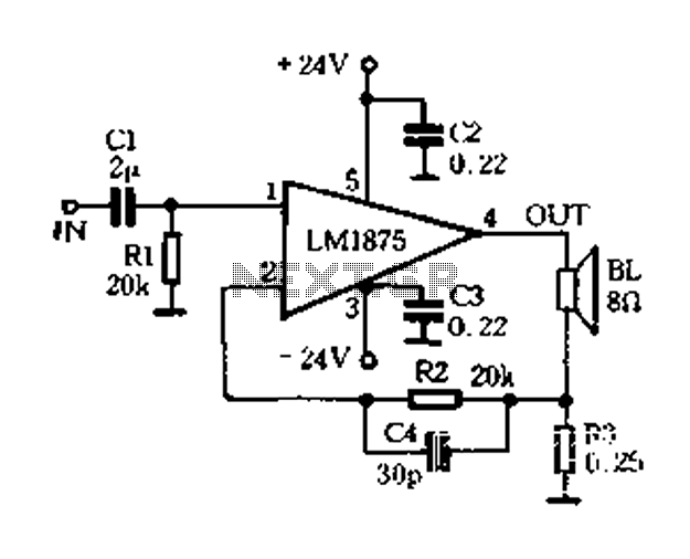
A current-sense amplifier is utilized to enhance the performance of the LM1875 current-mode amplifier circuit, as depicted in Figure 5-20. The resistor R3 and the series resistance of the speaker contribute to the current flowing through R3. This current...