
12v 10 LED battery monitor
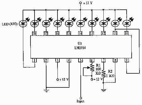
The circuit utilizes the LM3914, a popular LED bar graph/LED dot display driver, which is designed to provide a visual representation of an analog voltage level. This device operates in two modes: bar graph mode and dot mode, which can be selected by connecting the mode pin (pin 9) to either the positive supply voltage or ground.
Powering the LM3914 with its own dedicated battery is crucial for accurate voltage readings. This minimizes the potential for voltage drops or fluctuations that might occur if the circuit shares power with other components. The monitored battery should be connected to pin 5 of the LM3914, which serves as the input for the voltage to be measured.
To ensure proper operation, the circuit should include resistors with a tolerance of 5% or 10% and a power rating of 1/4-watt. These resistors can be used in conjunction with the LM3914 to set the reference voltage levels and to limit the current flowing through the LEDs, ensuring that they operate within their specified limits.
In a typical application, the output pins (pins 10 to 18) of the LM3914 are connected to a series of LEDs that visually indicate the voltage level across the monitored battery. Depending on the configuration, the number of lit LEDs will correspond to the input voltage, providing an intuitive display of the battery's state of charge.
For optimal performance, it is advisable to include decoupling capacitors near the power supply pins of the LM3914 to filter out any noise that may affect the accuracy of the readings. Additionally, a potentiometer can be integrated into the circuit to allow for calibration of the voltage range displayed by the LEDs, ensuring precise monitoring of the battery voltage.
This circuit can be effectively used in various applications, such as battery monitoring systems for portable devices, electric vehicles, or renewable energy systems, where knowing the battery voltage is crucial for maintaining operational efficiency and longevity.this circuit uses the LM3914 and should be powered by its own battery, otherwise you might get an innacurate reading. hook the to-be-monitored battery to pin 5 of the chip. all resistors are 5 or 10 percent tolerance, 1/4-watt 🔗 External reference
Related Circuits
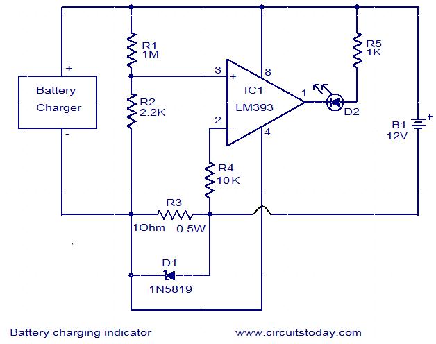
This simple circuit can be used to monitor whether a battery is charging. The voltage comparator IC LM393 is the core component of this circuit. The LED D1 will remain ON whenever there is at least 25 milliampere current...
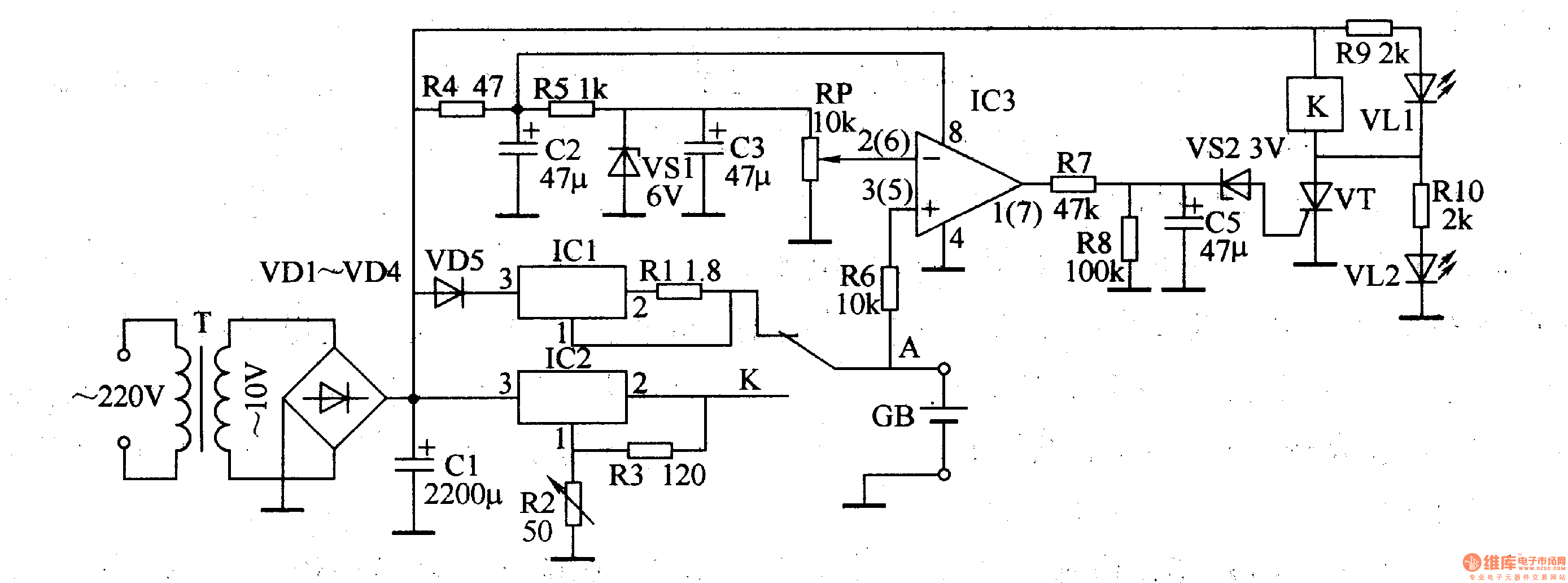
The lithium battery charger introduced in the example can charge a 6V lithium-ion battery in a constant current mode and switch to constant voltage charge mode when the battery voltage reaches 4.1V. The lithium battery charger circuit operates on...
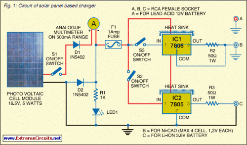
Switching to alternative power sources can lead to savings on electricity bills. The photovoltaic module or solar panel discussed here has a power output of 5 watts. Under full sunlight conditions, the solar panel generates 16.5V and can provide...
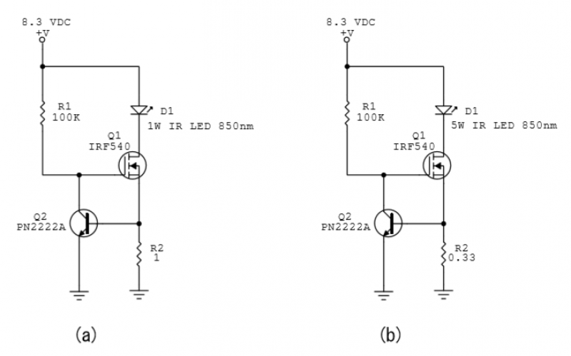
A constant-current power LED driver circuit is depicted in the schematic. Q1 is activated by R1 and functions as a variable resistor. Q2 serves as an “over-current” switch, while R2 establishes the maximum current. For the power LEDs utilized,...
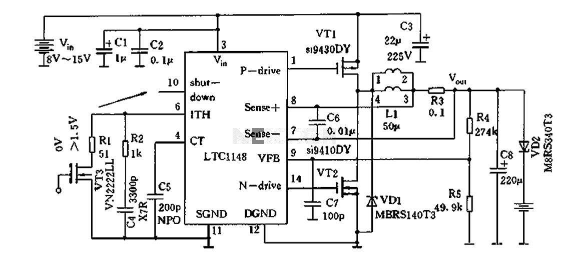
Efficient nickel-cadmium battery charger IC (LTC1148) circuit The LTC1148 is an integrated circuit designed for the efficient charging of nickel-cadmium (NiCd) batteries. This charger IC features a constant current/constant voltage (CC/CV) charging method, which is essential for optimizing the charging...
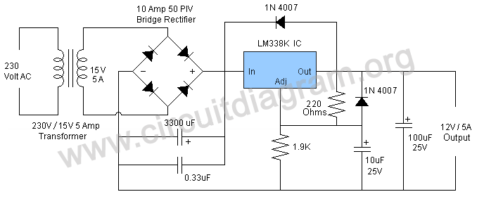
A 12V power supply is an essential and useful resource for laboratories, as it is employed by a wide range of electronic circuits and devices. A 12V power supply circuit can be constructed based on specific ampere requirements. A...
Warning: include(partials/cookie-banner.php): Failed to open stream: Permission denied in /var/www/html/nextgr/view-circuit.php on line 713
Warning: include(): Failed opening 'partials/cookie-banner.php' for inclusion (include_path='.:/usr/share/php') in /var/www/html/nextgr/view-circuit.php on line 713