
Power LED Driver

A heatsink is necessary for the IRF540 and the IR LED, particularly during 5W operation. For the 1W driver circuit, the forward voltage drop (Vf) across the LED is approximately 1.67V.
The current limiting resistor (R2) may be difficult to source and may lack the desired precision, especially for high currents. Consequently, an alternative circuit design is proposed. A fixed resistor of 1Ω is used as a current sensor. The voltage drop across this resistor is compared with a reference voltage to set the current.
This alternative circuit employs the voltage drop across R2 (referred to as VREF) to restrict the drain current of Q1. The drain current is limited to VREF/R3. For instance, if VREF is set to 1V, the drain current (ID) will be 1A. This configuration operates effectively for drain currents ranging from approximately 10mA to 1.7A.
In another configuration, three 1W IR LEDs are connected in series. This circuit operates with a 12.6VDC supply (from three series-connected 18650 batteries). The design with an 8.3VDC supply is ineffective for the three LED configuration because the lower supply voltage causes the MOSFET to operate in the linear mode. The supply voltage can be reduced to 10V.
A driver circuit was constructed using the architecture shown in the schematic with three 5W 850nm IR LEDs connected in series. The DC power supply consists of four 18650 batteries in series. The LED current is adjusted to 1400mA using R2. The updated circuit design is presented in the schematic.
The constant-current LED driver circuit utilizes a combination of transistors and resistors to manage the current delivered to the LEDs efficiently. The use of a heatsink for the IRF540 is critical, especially for higher wattage applications, to prevent thermal overload and ensure reliability. The variable resistor (Q1) allows for dynamic adjustment of current based on the feedback from the current sensor resistor (R2), which is essential for maintaining consistent brightness and preventing damage to the LEDs.
The introduction of a fixed resistor as a current sensor enhances the precision of current regulation, addressing the limitations faced with standard current limiting resistors. The ability to set a reference voltage (VREF) allows for easy adjustments to the maximum current, contributing to the versatility of this driver circuit across different LED configurations.
In summary, this LED driver circuit design emphasizes efficiency, reliability, and adaptability, making it suitable for various applications requiring precise control of LED current.A constant-current power LED driver circuit is shown in Fig. 1. Q1 is turned on by R1 and acts as a variable resistor. Q2 is an “over-current” switch and R2 sets the maximum current. For the power LEDs that I use, the 1W circuit draws about 440mA from the DC source, which corresponds to about 0.44V VBE threshold voltage for PN2222A. The 5W circuit draws about 1.33A and this also corresponds to about 0.44V VBE threshold. The circuit can be operated using two 18650 Li-Ion batteries in series.
A heatsink is required for IRF540 and the IR LED, especially for 5W operation. For the 1W driver circuit, the voltage drop Vf on the LED is about 1.67V.
Current limiting resistor (R2 in Fig. 1) may be hard to find and may not have the desired precision, especially for large currents. So I designed the circuit shown in Fig. 2. A fixed resistor of 1Ω is used as the current sensor. The voltage drop on this resistor is compared with a reference voltage to set the current.
Fig. 2. This circuit uses the voltage drop on R2 (let’s refer it as VREF) to limit the drain current of Q1.
The drain current is limited to VREF/R3. For example, VREF can be set to 1V for ID=1A. This circuit works nicely for ID from about 10mA to 1.7A.
Fig. 3. Three 1W IR LEDs are connected in series. This circuit uses a 12.6VDC supply (three 18650 batteries are in series). 8.3VDC design shown in Fig. 2 is not working properly for the three LED design because lower supply voltage cause MOSFET to be in the linear operation mode. Power supply can be lowered down to 10V.
I built a driver circuit using the architecture shown in Fig. 3. Three 5W 850nm IR LEDs are connected in series. DC power supply is formed by four 18650 batteries in series. LED current is adjusted for 1400mA using R2. The new circuit is shown in Fig. 5. By 4beowulf7 - [email protected]
Related Circuits
The circuit is designed to create a power amplifier that utilizes E80CC and EL34 vacuum tubes to achieve optimal performance, providing an output of 35 Watts. The power amplifier circuit employs E80CC and EL34 vacuum tubes, which are known for...

This circuit is for a temperature controlled constant current battery charger. It works with NICD, NIMH, and other rechargeable cells. The circuit works on the principle that most rechargeable batteries show an increase in temperature when the cells become...
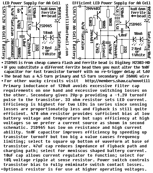
Efficiency can be increased by using a germanium transistor at the 33 ohm current sense resistor, and by using a proper torroid core in place of the crappy ferrite bead. Single AA cell powers two LEDs at constant current. The...

This design is directly reproduced from the manufacturer's datasheets; however, its application in this context is quite innovative. Originally intended for high-performance applications... This circuit design utilizes components specified in the manufacturer's datasheets, ensuring adherence to the recommended specifications for...
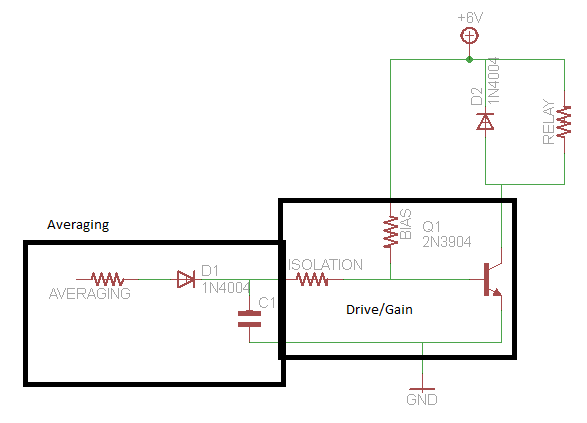
A circuit that activates a relay upon detecting audio pulses from one channel of an MP3 player. The intention is to synchronize recorded audio pulses with music to control a motor for mouth movement. For a stereo player, music...
A simple and interesting project schematic for a cell phone signal-activated LED circuit. The circuit will illuminate an LED when a call is made from a cell phone. This cell phone signal-activated LED circuit utilizes a basic principle of detecting...