
12V DC Voltage Doubler Circuit

The circuit operates by employing a configuration that doubles the input voltage through a combination of capacitors and diodes, achieving the desired output voltages. The primary components include a transformer, which is not always necessary in a simple doubler circuit, but can be used for isolation and voltage scaling. The diodes are arranged in a specific manner to allow for the rectification and regulation of the output voltages.
In the case of the 12V to 24V conversion, the circuit typically utilizes a full-wave rectifier configuration, where two diodes are used to conduct during each half-cycle of the AC waveform, effectively doubling the output voltage. Capacitors are placed in parallel to store the charge and smooth out the output, ensuring a stable DC voltage.
For the 18V output, additional regulation may be required, which could involve the use of a linear voltage regulator or a switching regulator circuit. This component would help maintain a consistent output voltage despite variations in load or input voltage.
Power transistors, whether PNP or NPN, are employed to switch the current through the circuit, allowing for efficient control of the output voltage levels. The choice of transistor will depend on the required current handling capabilities and the specific characteristics of the circuit design.
Overall, this circuit design provides a versatile solution for applications requiring multiple DC voltage levels derived from a single DC source, making it suitable for various electronic projects and systems. Proper thermal management and component ratings should be considered to ensure reliable operation under load conditions.This is the circuit diagram of DC voltage doubler / DC converter. The circuit will convert 12VDC power supply to become a 24VDC at and 18VDC. Almost any PNP or NPN power transistors should be work for this circuit. 🔗 External reference
Related Circuits
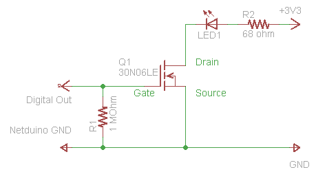
The process of driving an LED involves using a Power MOSFET to control the LED's state (On and Off) via a digital signal. This guide provides a step-by-step approach to wiring the circuit on a breadboard, which serves as...
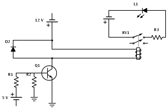
Create a circuit that enables the activation of a relay to control an LED. The relay operates at 12 V, while the available input voltage is 5 V. An NPN transistor will be utilized to switch the power to...
This voltage-to-frequency converter circuit features a voltage-controlled oscillator with a deviation of 0.5%. The integrated circuit IC1 functions as a multivibrator, generating rectangular impulses of equal width. The output frequency is adjustable via the U1 voltage. The D3 diode...
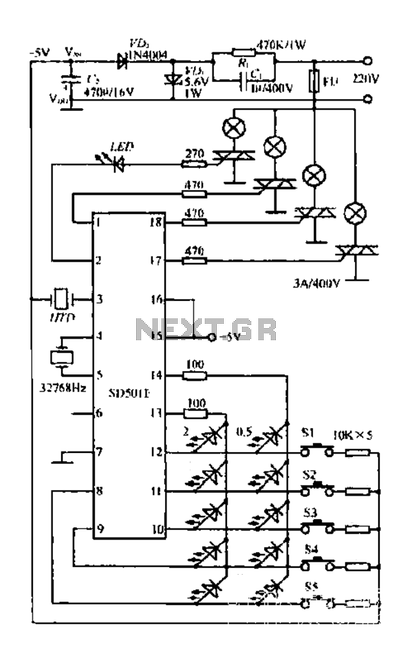
The FIG SD501E is a J tie fan integrated circuit (IC) characterized by progressive timing and three operational modes: strong, medium, and weak. It features three types of output settings and includes an electrical swing mechanism. The device is...
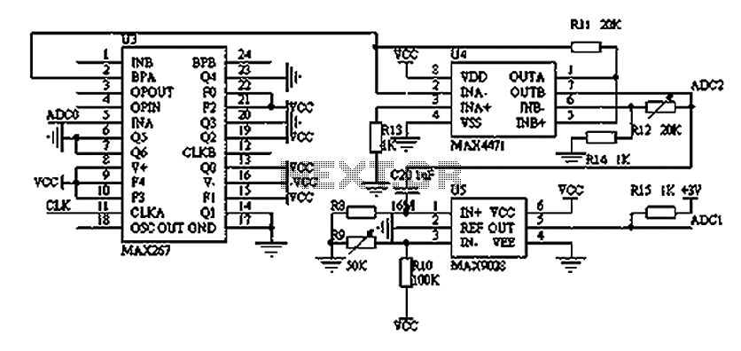
The filtering and amplifying circuit consists of two main components. The MAXIM MAX267 filter is an integrated circuit that can function as a low-pass, band-pass, high-pass filter, and other configurations, offering superior performance compared to traditional op-amp filters. The...
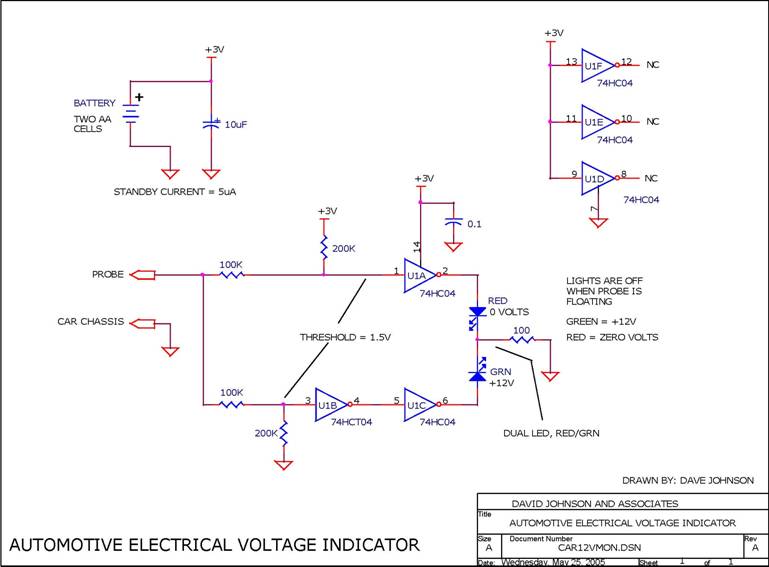
When troubleshooting the 12V electrical system of an automobile, it is beneficial to have a simple voltage indicator tool instead of a voltmeter. This electronic circuit is powered by two AA batteries or two N cells, providing sufficient energy...