
relay In a circuit being switched by an NPN transistor do power supply and input need the same ground

To construct the described circuit, the following components are necessary: an NPN transistor (such as the 2N3904), a relay rated for 12 V, an LED, a current-limiting resistor for the LED, and a power supply consisting of 8 AA batteries. The circuit will also require a microcontroller, such as an Arduino, to control the operation of the transistor.
1. **Power Supply Configuration**: The 8 AA batteries will be arranged in series to provide a total output of 12 V. The positive terminal of the battery pack will be connected to one terminal of the relay coil. The other terminal of the relay coil will be connected to the collector of the NPN transistor. The emitter of the transistor will connect to the common ground shared with the Arduino.
2. **Transistor Control**: The base of the NPN transistor will be connected to a digital output pin on the Arduino through a current-limiting resistor (typically around 1 kΩ). This resistor is essential to protect the Arduino from excessive current. When the Arduino outputs a HIGH signal, it will turn on the transistor, allowing current to flow from the collector to the emitter, thus energizing the relay coil.
3. **Relay and LED Connection**: The relay will act as a switch for the LED. When the relay is activated, it will close its contacts, allowing current to flow through the LED. The LED should be connected in series with an appropriate current-limiting resistor to prevent it from drawing too much current, which could damage the LED. The other end of the LED will connect to the positive terminal of the 12 V power supply.
4. **Grounding**: To ensure proper operation, the grounds of both the Arduino and the 12 V power supply must be connected together. This can be accomplished by connecting the negative terminal of the battery pack to the ground pin of the Arduino. This common ground is crucial for the correct functioning of the control circuit, as it ensures that the voltage levels are referenced correctly.
This circuit design allows the Arduino to control a 12 V relay with a 5 V signal, enabling the switching of higher voltage devices like an LED while maintaining safety and functionality.Make a circuit that will allow me to switch on a relay that will turn on an LED. However, the relay is rated for 12 V, and I only have an input of 5 V, so I`m using an NPN transistor. to switch the power to the relay on and off. Here`s the schematic: If my 12 V power supply is 8 AA batteries (not sustainable, but I`m just using it for testing), how would I connect that to the same ground as the arduino, instead of the negative side of the batteries
🔗 External reference
Related Circuits
A DIY RF decibel (or power) meter is an essential instrument in any radio workshop. However, accurate, wideband models can be quite costly. A DIY RF decibel meter serves as a valuable tool for measuring the power levels of radio...
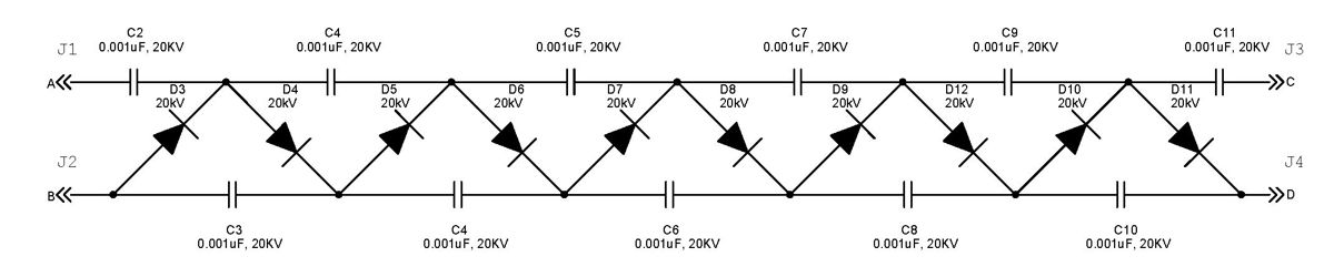
The Cockcroft-Walton multiplier employs a series of diodes and capacitors arranged in a cascade to generate a high-voltage DC potential from an AC input. This circuit topology utilizes diodes to charge capacitors in parallel and discharge them in series....
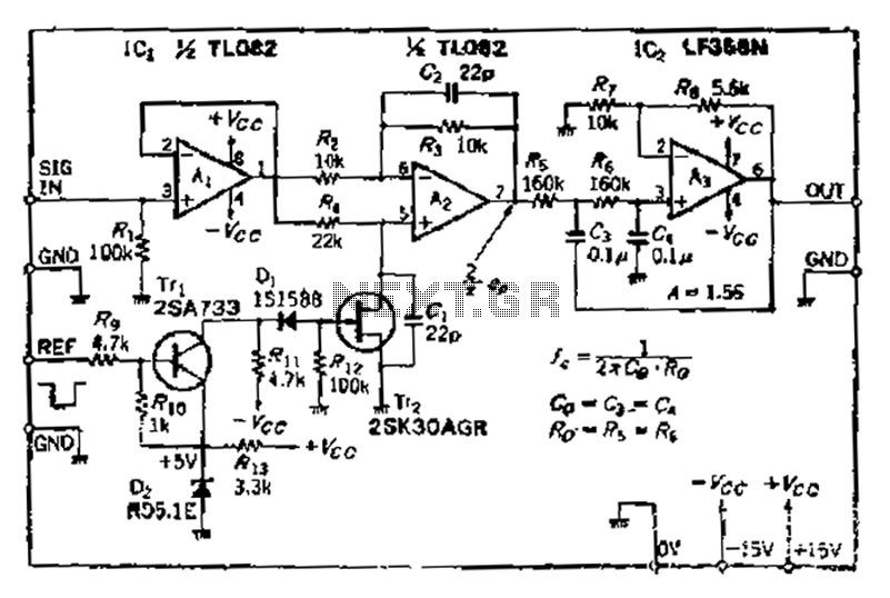
After turning off TT2, the input signal enters through chi Az, where the input resistance is very high and reaches the same potential. The inverting input terminal must also be associated with this movement. Therefore, Trr functions as a...
Connect a 12V fan to this circuit that consumes 70mA (0.07A), ensuring the circuit can supply at least that amount of current. There appears to be a misunderstanding regarding the analysis. The voltage drop across the resistor equals the...
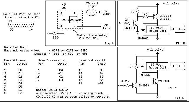
Below are three examples of controlling a relay from the PC's parallel printer port (LPT1 or LPT2). Figure A shows a solid state relay controlled by one of the parallel port data lines (D0-D7) using a 300 ohm resistor...
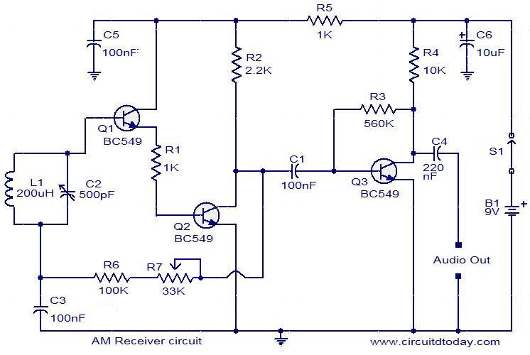
The following circuit illustrates an AM receiver capable of operating within the frequency range of 550 to 1100 KHz. Features include adjustments for sensitivity and selectivity of the circuit. The AM receiver circuit designed for the frequency range of 550...