
12V Lamp flasher circuit

The circuit operates by utilizing a BC557 transistor as a switching element, which is responsible for controlling the ON and OFF states of the circuit. The transistor is connected to a control circuit that dictates the flashing frequency, allowing for customizable blinking patterns. The IRF530 MOSFET is employed to handle higher current loads, providing efficient drive capability for the connected lamps.
In terms of component connections, the base of the BC557 transistor is typically connected to a resistor that limits the base current, ensuring that the transistor operates within its safe limits. The emitter is connected to the ground, while the collector is linked to the gate of the IRF530 MOSFET. The source of the MOSFET connects to the ground, and the drain is connected to the load, which in this case are the 12V lamps.
To ensure that the total load does not exceed 2 Watts, the circuit designer should calculate the number of bulbs based on their individual wattage ratings. For example, if using 1W bulbs, a maximum of two bulbs can be connected in parallel. Additionally, appropriate heat sinking may be required for the MOSFET, depending on the total current drawn by the lamps, to prevent thermal overload.
The circuit can be powered from a standard 12V automotive battery, making it suitable for various automotive applications. Overall, this design provides a reliable method for creating flashing light effects in vehicles, enhancing visibility and safety.Here is a simple yet powerful circuit that can be used for flashing 12V lamps especially that is used on automobiles. The flashing circuit is based on transistor Q1(BC557) and MOSFET Q2 (IRF530) where the Q2 provides the necessary drive for the lamp.
Any number of bulbs can be flashed using this circuit provided that the total load must not exceed 4 2 Watts. 🔗 External reference
Related Circuits

The TDA4866 is a 90-color power amplifier designed for vertical deflection systems, operating at a frequency range of 50 to 160 Hz. The CRMM circuit is implemented to ensure a high current drive input. The amplifier features a dual...
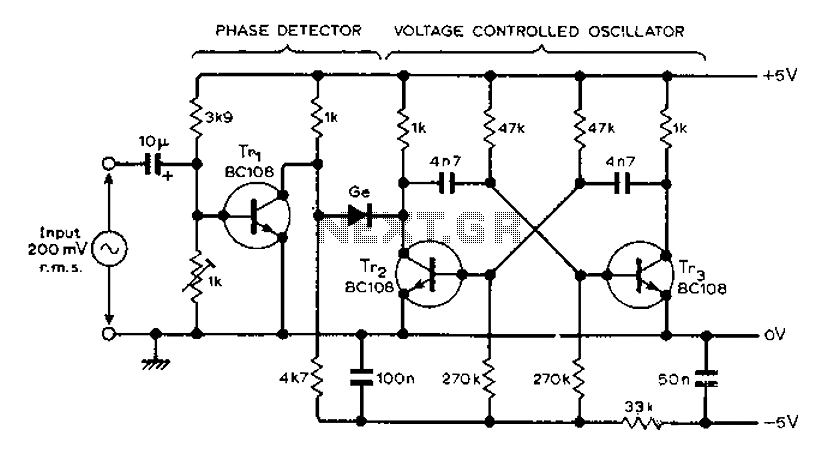
The circuit MVBR utilizes a traditional two-transistor configuration along with other components to create a simple phase-locked loop (PLL). The transistor TR1 and diodes function as a logic gate, activating during half periods of the input waveform of the...

This is the circuit diagram of a line follower/line tracker robot. The circuit is derived from tutorial documentation, which can be downloaded at the end of this article. The line follower robot utilizes eight proximity sensor modules. Each sensor...

The circuit is built around a single 4093 quad 2-input NAND Schmitt trigger. Two gates from that quad package (U1-a and U1-b) are configured as a set-reset flip-flop. The 4093 integrated circuit (IC) contains four independent 2-input NAND gates with...

Direct derivation of 5 to 24 Vdc from AC mains without a transformer is possible with this circuit. Note that a direct mains connection to the DC output exists. Suitable safety precautions must be taken. This circuit design allows for...

This circuit lights up ten bulbs sequentially, first in one direction and then in the opposite direction, creating an appealing visual effect. In this circuit, gates N1 and N2 form an oscillator. The output of this oscillator serves as...