
ATmega8535 Line Follower Robot circuit diagram

The line follower robot circuit is designed to autonomously navigate along a predetermined path, typically marked by a contrasting line on the ground. The core components of this circuit include eight proximity sensor modules, which are strategically positioned to detect the line's presence. Each sensor module consists of a photodiode that senses light reflection. When the robot is on the line, the sensors detect the reflected light, sending signals to the microcontroller, which processes the information to determine the robot's direction.
The L298 motor driver plays a crucial role in controlling the movement of the robot. It can drive two DC motors simultaneously, allowing for differential steering. This means that the speed and direction of each motor can be adjusted independently, enabling the robot to turn and navigate effectively. The L298 can handle a maximum output current of 2A per motor, making it suitable for small to medium-sized motors commonly used in robotic applications.
The design of the circuit also includes power management considerations, ensuring that the sensors and motors receive adequate voltage and current for optimal performance. The microcontroller, typically an Arduino or similar platform, interfaces with the sensor modules and motor driver, executing the logic required to keep the robot following the line. The overall architecture of the circuit is modular, allowing for easy modifications and upgrades as needed for advanced functionalities or improved performance.
In summary, the line follower robot circuit is a well-structured design that integrates sensor technology with motor control to achieve autonomous navigation, making it an excellent platform for educational purposes and robotics experimentation.This is the circuit diagram of Line Follower / Line Tracker robot. The circuit taken from the tutorial documentation. You may download the full tutorial at the end of this article. The line follower robot use 8 pieces of proximity sensor module. The sensor module use photodioda for detecting the reclection of light from the line/floor. The motor d river L298 able to control the motor with current output up to 2A for single DC motor. For double DC motors, there should be up to 1A for each output channel. This motor driver is very good for small and medium DC motor. L298 is great motor driver for small and medium size or robot such as line follower robot and fire fighter robot. 🔗 External reference
Related Circuits
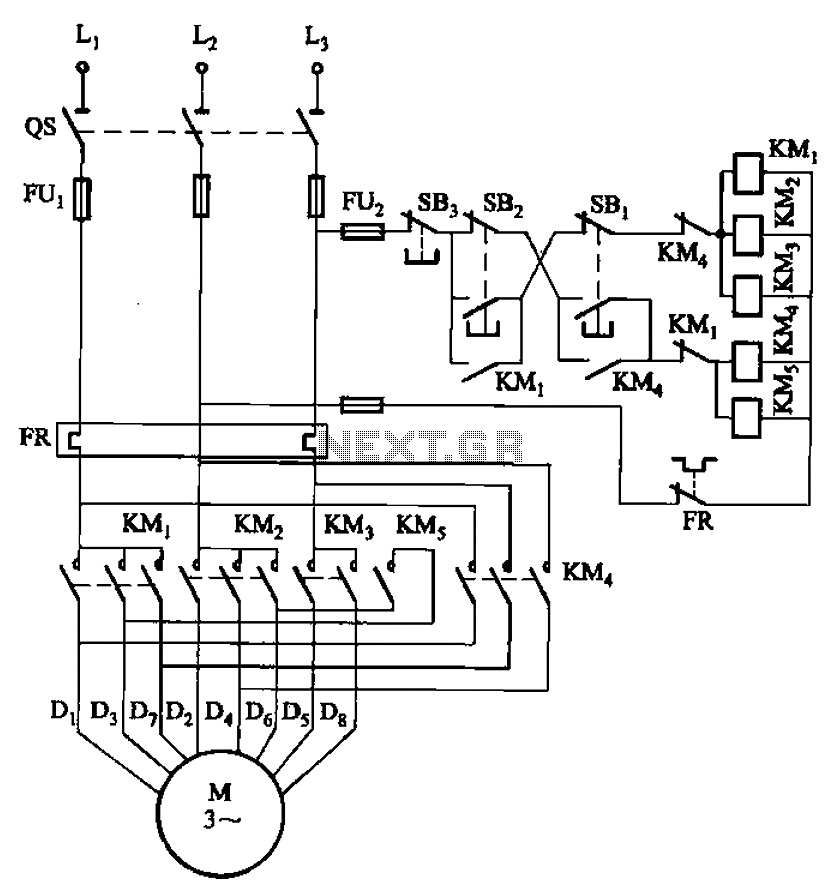
The circuit illustrated in Figure 3-104 features SB2, which functions as the low-speed operation button, and SBi, which serves as the high-speed operation button. The circuit design utilizes two distinct operational buttons, SB2 and SBi, to control the speed of...
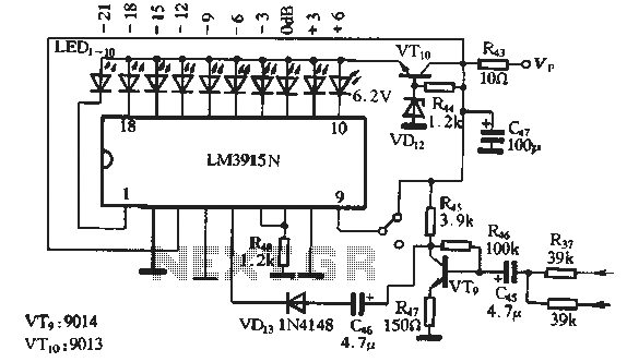
The circuit features a manual recording level control function. When in recording mode, the recording level is indicated by the LM3915N. The sound recording circuit, as illustrated in Figure 3-17, employs an RC network and an associated audio recording...
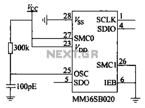
The chip power later, when the strobe IEB is held low, allows for the transfer of memory to the instruction, address, and read or write data. All operations regarding order, address, and data transfer initiate from the least significant...
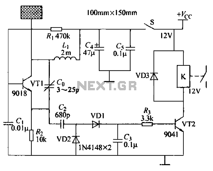
A capacitive proximity controller typically consists of a radio frequency oscillation circuit and a detection plate. The circuit is constructed using discrete components for capacitive proximity sensing detection. The transistor VT1, along with surrounding components, forms a radio frequency...
This is a component of a 100W RF amplifier. This circuit is constructed using the RF power transistor BLY94. Components include the BLY94 transistor, inductor, and others. The 100W RF amplifier circuit utilizing the BLY94 transistor is designed to amplify...
This circuit is straightforward. The initial 555 timer prevents the second timer from being activated while the first is operational. Drive the circuit with a simple 12-volt power supply. The circuit utilizes two 555 timer integrated circuits (ICs) configured in...