
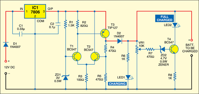
12V lead acid battery charger by LM317K

The described circuit utilizes the LM317K voltage regulator, which is an adjustable three-terminal device capable of delivering a stable output voltage. In this application, it is configured to output approximately 13.5 volts, which is essential for charging a 12V lead-acid battery. The circuit typically includes a few additional components such as resistors to set the output voltage, capacitors for filtering, and a diode to prevent reverse current flow.
To construct the circuit, the input voltage should be higher than the desired output voltage to account for the dropout voltage of the LM317K. A suitable transformer or power supply can be used to provide the necessary input voltage, ideally around 15V to 18V AC, which will be rectified and filtered to provide a DC input to the LM317K.
The charging current is regulated to 1A, which is suitable for the 7.5Ah battery, ensuring that the battery can be charged in approximately 8 hours. This is achieved by selecting the appropriate resistor values in the circuit. It is critical to monitor the charging process to prevent overcharging, which can damage the battery. A simple LED indicator can be included in the circuit to signal when charging is in progress.
Overall, this battery charger circuit is efficient and cost-effective, making it an excellent choice for those needing to charge lead-acid batteries safely and effectively. The simplicity of the design allows for easy assembly and troubleshooting, making it accessible for hobbyists and engineers alike.Today a close friend visits tell want Dry cell lead acid battery charger circuit 12V 7. 5hA sizes. In model to are simple and economize with. I then advise this circuit try build see. By use the integrated circuit voltage regulator the number is highly popular be, LM317K. This circuit has the principle is simple be heal level voltage be stable 13. 5 Volt. Because battery must use voltage tall more then charger get follow want. Which battery of a friend must use current 1A take time charging about 8 hour then will have the electric energy with full speed ahead. The detail is other, see in the circuit. 🔗 External reference
Related Circuits
There is no need to be disappointed the next time your digital camera displays a low battery indication during a picnic trip. Simply connect this digital camera adapter to the cigarette lighter outlet of your car and link the...
If a page name is not selected by pressing the button, the previously selected page name continues to be used. The value is stored in EEPROM and may be changed at any time. When the unit is first powered...
This discussion assists in selecting the most appropriate microprocessor supervisor integrated circuit (IC) for specific applications and provides solutions for various common supervisory issues encountered with microprocessors. Microprocessor supervisor ICs are critical components in ensuring the reliable operation of microprocessor-based...
Switching to alternative power sources can lead to savings on electricity bills. The photovoltaic module or solar panel discussed here has a power output of 5 watts. Under full sunlight conditions, the solar panel generates 16.5V and can provide...
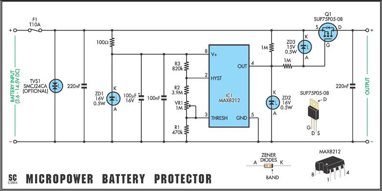
Protect expensive batteries from discharge damage with this mini-sized electronic cutout switch. It consumes minimal power and can be adapted to accommodate a wide range of battery voltages. In May 2002, Silicon Chip introduced the "Battery Guardian," a project...
This article presents a driver circuit for a 12V, 5W fluorescent lamp. The circuit utilizes a standard 220V to 10V step-down transformer operated in reverse to achieve a 12V output. The driver circuit for a 12V, 5W fluorescent lamp is...