
12V DC Fluorescent Lamp Circuit

The driver circuit for a 12V, 5W fluorescent lamp is designed to efficiently convert high voltage AC power to a lower voltage suitable for the lamp operation. The use of a standard 220V to 10V step-down transformer in reverse is a practical approach, as it allows for the manipulation of voltage levels without the need for additional complex circuitry.
The circuit typically consists of the following components: a transformer, a rectifier, a filter capacitor, and a ballast resistor. The transformer is connected to the AC mains supply, and when operated in reverse, it steps down the voltage to 12V. The output from the transformer is then fed into a rectifier circuit, which converts the AC voltage to DC. A common choice for the rectifier is a bridge rectifier configuration, which ensures that the output is smooth and stable.
Following the rectifier, a filter capacitor is employed to eliminate any remaining ripple in the DC output, providing a more stable voltage for the fluorescent lamp. The value of the filter capacitor must be selected carefully to balance between size and performance, ensuring that the output voltage remains within acceptable limits for the lamp.
The ballast resistor is essential for controlling the current flowing through the fluorescent lamp, preventing it from drawing excessive current, which could lead to damage or reduced lifespan. The resistor value is determined based on the specifications of the lamp and the desired operating conditions.
This circuit design is advantageous due to its simplicity and the availability of standard components, making it accessible for various applications. Care should be taken during the implementation to ensure that all components are rated appropriately for the voltages and currents involved, as safety is paramount when working with electrical circuits.In this article I will offer driver circuit for 12 V/5Watt fluorescent lamp, this circuit used a normal 220 to 10V stepdown transformer in reverse to step 12V. 🔗 External reference
Related Circuits

This circuit is capable of delivering approximately 200W of power output, produced by Phillips Semiconductor. It utilizes two PHP1BN11QT devices and operates with an input voltage range of 30 to 45 Volts DC. The described circuit is a high-power switching...
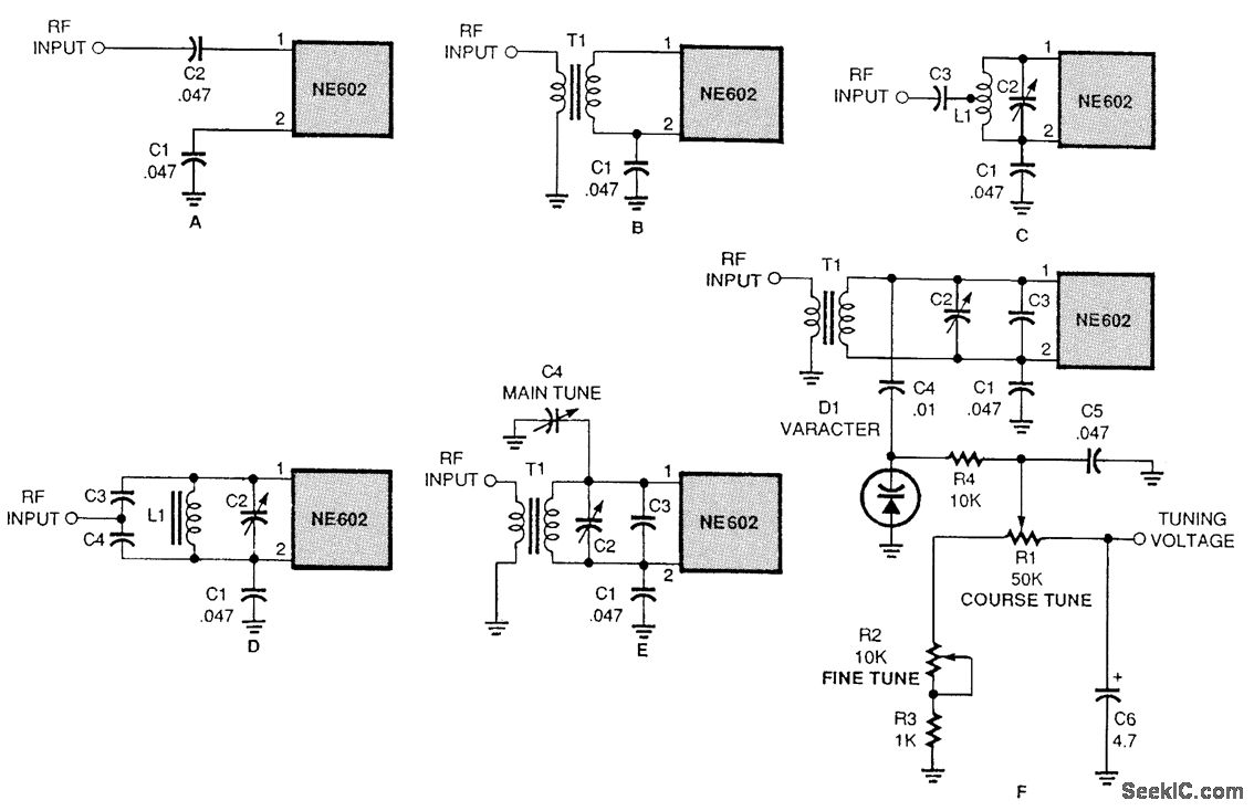
There are several methods to input a signal into the NE602. Simple untuned approaches (a and b) are viable. For tuning to a specific frequency, an LC resonant circuit with ungrounded trimmer capacitors (c and d) or grounded variable...
This precise one-pulse-per-second clock is constructed using a few common components and is driven by a 50 or 60 Hertz mains supply, without any direct connection to it. It produces a beep or metronome-like click and/or a visible flash...

This circuit is used for a Digital Radar Speedometer. It allows for the measurement of the speed of any moving object, particularly vehicles such as cars. The speed is displayed in kilometers per hour (KPH) with a three-digit display....
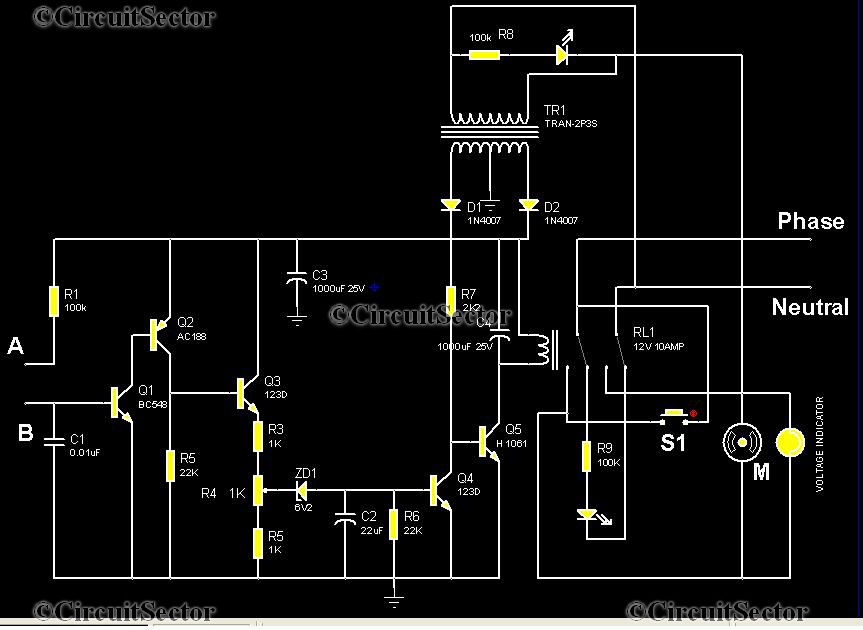
This is an automatic water tank controller designed to manage the operation of a water pump using a 12V 10A relay. When the water level in the tank creates a short circuit between points A and B in the...
The circuit (before flameout) worked like this: device Q1 is a triac, which is a power-switching device. When triggered, it switches to a fully conducting state and stays that way until the current passing through it goes to zero....