
12V Led Car Battery Monitor

This circuit functions as a battery voltage monitoring system, specifically designed to provide visual indications of battery charge levels through a series of light-emitting diodes (LEDs). The primary component of the circuit is a 10K trimmer potentiometer, which allows for precise calibration of the voltage thresholds that correspond to the various LED indicators.
The circuit is powered by a nominal input voltage of 12.65 volts, which is the threshold for indicating a fully charged battery. When this voltage is applied across the circuit, the trimmer potentiometer is adjusted until LED 10 is illuminated, confirming that the circuit is correctly calibrated for the upper limit of battery capacity.
As the input voltage decreases, the circuit is designed to sequentially activate the LEDs, providing a visual representation of the battery's remaining charge. Specifically, when the input voltage drops to approximately 11.89 volts, LED 1 will illuminate, signaling that the battery is nearing its minimum operational capacity.
The LEDs are categorized by color to represent different charge levels:
- Green LEDs indicate that the battery capacity is above 50%, suggesting a healthy charge.
- Yellow LEDs indicate a battery capacity between 30% and 50%, which may require monitoring.
- Red LEDs signal that the battery capacity is below 30%, indicating that recharging is necessary to avoid potential damage to the battery.
This circuit is particularly useful in applications where battery management is critical, providing an easy-to-read visual status of battery charge levels, thereby enhancing user awareness and ensuring safe operation of battery-powered devices.This simple circuit makes it posible to monitor the charging process to a higher level. Final adjustsments are simple and the only thing needed is a digital voltmeter for the necessary accuracy. Connect an input voltage of 12.65 volt between the positive and negative poles and adjust the 10K trimmer potentiometer until Led 10 lights up.
Lower the voltage and in sequence all other Led's will light up. Check that Led 1 lights up at approximately 11.89 volts. At 12.65 volt and higher the battery is fully charged, and at 11.89 is considered 'empty'. The green Led's indicate that the battery capacity is more than 50%, the yellow Led's indicate a capacity of 30% - 50% and the red Led's less that 30%. This circuit 🔗 External reference
Related Circuits
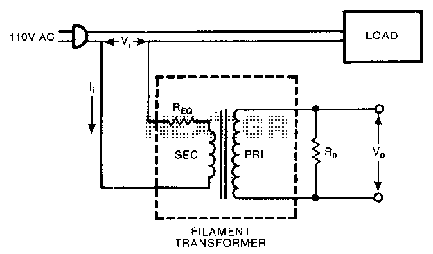
A low-cost filament transformer provides a linear indication of the load current in an AC line. This method causes a slight series voltage drop over a wide range of load currents. A low-cost filament transformer is utilized in applications requiring...
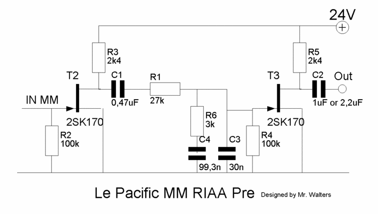
This document describes a DIY build of the Boozhound Laboratories JFET Phono Preamplifier constructed on a stripboard. The BHL preamp is primarily based on the Le Pacific RIAA phono preamplifier circuit. The construction utilizes brown polypropylene capacitors sourced from...
When we step on the car's brake, then together with the classic rear STOP, the third STOP which is situated in the middle of the back half of the car also switches ON. This is the classic function, found...
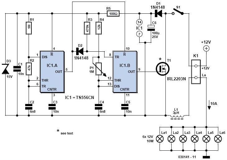
A light dimmer is quite uncommon in a caravan or on a boat. This document outlines how to create one, allowing for mood adjustment when needed. A light dimmer circuit is an essential component for enhancing the ambiance in confined...
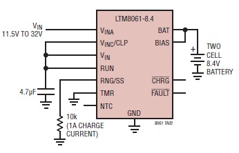
A simple and efficient lithium battery charger and monitoring system can be designed using the LTM8061 integrated circuit from Linear Technology. The LTM8061 is a high-efficiency 32V, 2A module standalone lithium battery charger optimized for one- and two-cell packs,...

This circuit is a precision amplifier with digital control, designed for signal conditioning of low-output transducers operating in the millivolt range. The resistors R3 to R6 can be user-selected, with values ranging from 1 kilo-ohm to 1 mega-ohm, allowing...