
12V Light Dimmer Circuit

A light dimmer circuit is an essential component for enhancing the ambiance in confined spaces such as caravans and boats. This circuit allows users to adjust the brightness of lighting fixtures, contributing to a more comfortable and personalized environment. The design of a light dimmer typically involves the use of a variable resistor or a solid-state device, such as a triac, which regulates the power delivered to the light source.
In a basic dimmer circuit, the primary components include a triac, an optoisolator, a variable resistor (potentiometer), and a few passive components like resistors and capacitors. The triac serves as a switch that can control the AC voltage supplied to the light bulb. By adjusting the variable resistor, the phase angle of the AC signal can be altered, effectively reducing the voltage and current flowing to the light fixture, which dims the light output.
The optoisolator is used to provide electrical isolation between the control circuit and the high-voltage AC circuit, enhancing safety. It allows a low-voltage control signal to trigger the triac without direct electrical connection, minimizing the risk of electric shock.
In terms of implementation, the circuit can be connected in series with the light load. When the potentiometer is adjusted, it changes the trigger point of the triac, thus controlling when the triac turns on during each AC cycle. This method is efficient and allows for smooth dimming without flickering.
Overall, the integration of a light dimmer in a caravan or boat not only increases the versatility of lighting options but also contributes to energy savings and extended lifespan of lighting elements.A light dimmer is quite unusual in a caravan or on a boat. Here we describe how you can make one. So if you would like to be able to adjust the mood when y.. 🔗 External reference
Related Circuits

Most consumer electronic devices utilize infrared remote controls for convenient operation. The carrier frequency of these remote controls typically ranges from 36 kHz to 38 kHz. Control codes are transmitted to the device's receiver in a serial format, which...
This 5-volt Switch Mode Power Supply circuit utilizes an integrated circuit (IC) from National Semiconductor, which specializes in the production and design of ICs for switch-mode power supply applications. The 5-volt Switch Mode Power Supply (SMPS) circuit is designed to...
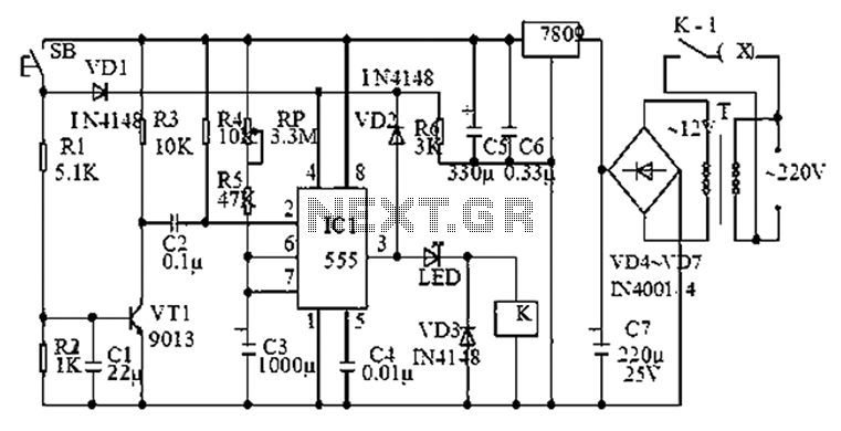
The 555 timer is commonly used in time-based circuit designs, particularly in monostable configurations. This setup is straightforward and requires only a few resistors and capacitors to achieve triggering. However, external interference can affect the operation of the circuit...
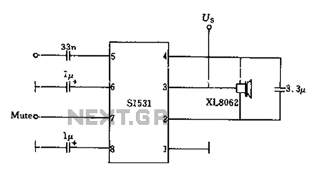
The battery voltage is 1V for a low-frequency amplifying circuit, which can operate with a power supply voltage ranging from 1V to 1.7V, making it suitable for use with small batteries. The circuit provides an output power of 80mW...
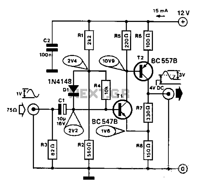
Commonly used for cameras or computers with black and white television connections, the amplifier has a gain of 3 and a bandwidth of 10 MHz. The described circuit is an amplifier designed for applications involving cameras or computers that interface...
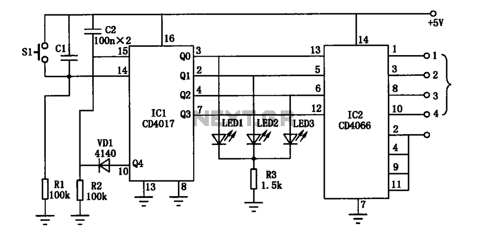
The electronic circuit diagram consists of the CD4017 and CD4066 components configured as a switch circuit. The CD4017 is a decade counter integrated circuit (IC) that can drive up to ten outputs, sequentially activating them based on clock pulses. It...