
The battery voltage is low frequency amplifying circuit diagram 1v

The low-frequency amplifying circuit is engineered to function efficiently within a minimal voltage range, making it particularly advantageous for portable applications where space and power supply options are limited. The circuit architecture typically includes a differential amplifier stage followed by a class D amplifier stage, ensuring high efficiency and low power consumption.
Key components of the circuit include operational amplifiers or dedicated audio amplifier ICs, which are chosen for their low voltage operation and high performance. The output stage is configured to drive speakers with a nominal impedance of 4 ohms, allowing for effective sound reproduction in compact audio devices.
The power supply design incorporates bypass capacitors to stabilize the voltage and minimize noise, enhancing audio quality. Additionally, the circuit may integrate feedback mechanisms to optimize gain and reduce distortion, ensuring that the output signal remains faithful to the input audio source.
This low-voltage amplifying circuit is particularly suitable for applications in portable audio devices, such as small radios, handheld speakers, or any battery-operated sound system where efficiency and compactness are critical. The ability to operate effectively at voltages as low as 1V opens up possibilities for innovative designs in consumer electronics, where conventional power sources may not be feasible. As shown in the battery voltage is 1v low frequency amplifying circuit, the circuit can operate at 1 ~ 1.7V power supply voltage, it can be powered by small batteries. Output p ower is 80mW, 48% efficiency. Adapted to drive the intermediate tap speaker (4 ohms X2), the battery voltage is 1.2V ICs.
Related Circuits
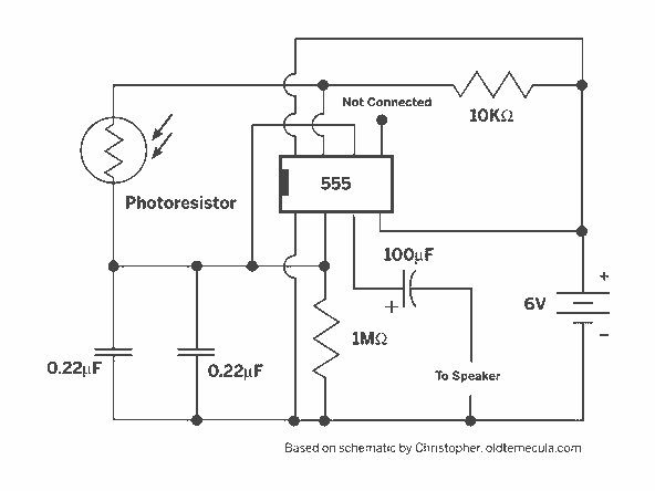
A light Theremin constructed using an oscilloscope panel, enhanced with a Joule Thief circuit. The design incorporates a 10 K variable resistor for pitch control and a 20 K variable resistor for volume control. The circuit is powered by...
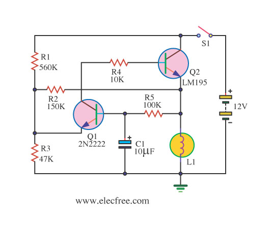
If you require a small lamp that flashes for general use, there are numerous options available. Today, three lamp flasher circuits will be presented. The three lamp flasher circuits can be designed using different components and configurations, each offering unique...
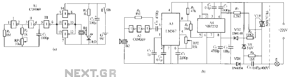
Remote control dimmer lights consist of two parts: an ultrasonic transmitter and an ultrasonic remote control dimmer receiver. The ultrasonic wave transmitter circuit is detailed in A 229 (a). It includes components such as R, R., RP1, and C,...
The receiver input circuit is powered by a 60Ω generator. A low-pass filter is employed to permit the entire frequency range while maintaining uniform sensitivity. The receiver input circuit is coupled with a transmitter inductive component (Ri = 60Ω)....
The metal detector circuit comprises several key components, including a power circuit, a sine wave oscillator, a PLL (phase-locked loop) circuit, and a hybrid amplifying circuit. The power circuit is made up of batteries GBI and GB2, filter capacitors...
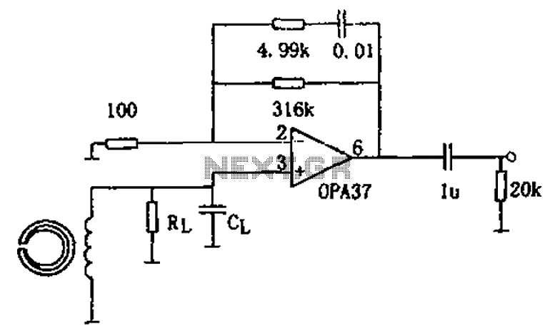
The circuit is a 90s common recorder head amplifier circuit that utilizes the ultra-low noise precision operational amplifier OPA37 as a preamplifier. This circuit is capable of providing standard NAB equalization. At a frequency of 1 kHz, it achieves...