
12V Neon Lamp Circuit

Neon lamps operate on the principle of gas discharge, where a low-pressure gas, typically neon, is contained within a glass tube. When a high voltage is applied across the electrodes at either end of the tube, it creates an electric field strong enough to ionize the gas. This ionization process transforms the neutral gas atoms into positively charged ions and free electrons, allowing current to flow through the gas. The initial high voltage required for this process is often in the range of several hundred volts.
Once the gas is ionized, the neon lamp transitions to a conductive state, resulting in a significant reduction in the voltage across the lamp, stabilizing around 40 volts. This lower operating voltage allows the lamp to maintain illumination with minimal power consumption. The characteristic glow of a neon lamp is due to the recombination of electrons and ions, which emits light at specific wavelengths.
In practical applications, neon lamps are commonly used as indicator lights, in displays, and for decorative lighting. They are known for their longevity and reliability, making them suitable for various electronic circuits that require visual signaling. The circuit design for a neon lamp typically includes a series resistor to limit the current flowing through the lamp, ensuring safe operation and preventing damage from excessive current. Additionally, a transformer or a high-voltage power supply may be used to provide the necessary voltage for initial ionization.Neon lamp or tube lamp need high voltage to trigger the ionization of the gas inside the tube. After the ionization occurs, the voltage drops around 40 volts.. 🔗 External reference
Related Circuits
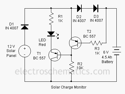
This add-on circuit can be attached to the solar charger to indicate whether the battery is charging. It lights a red LED to signal that the battery is charging. The described add-on circuit serves as a visual indicator for the...
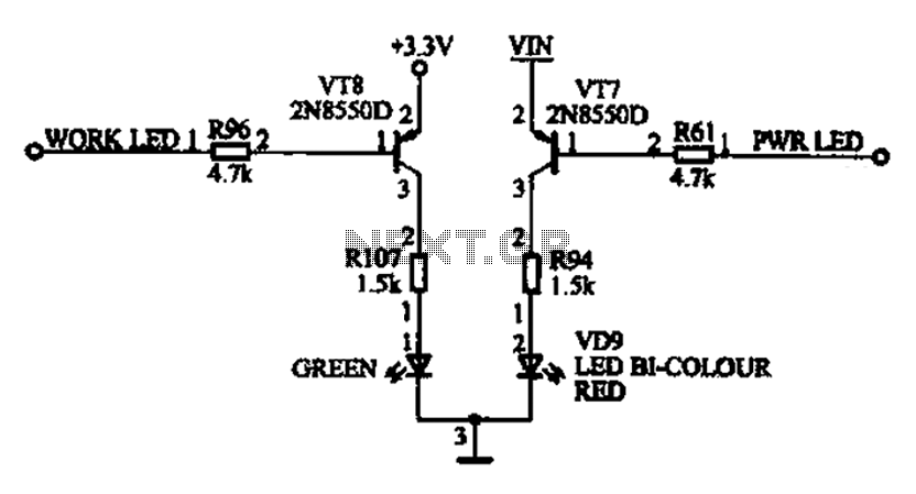
The ACER PM02 MP4 machine features a voltage status indicator circuit. When power is supplied, a red LED illuminates, indicating that the device is powered on. Upon entering operational mode, a green LED lights up. The voltage status indicator circuit...
This clock timer utilizes a PIC16F628 microcontroller to display a 3.5-digit time format and control an external load. It is programmable to time intervals from 1 to 59 minutes. The clock features a calendar that accounts for leap years...
GND and VCC are positioned perpendicularly to the other pins in the circuit diagrams, while the actual Z80 is a DIP with no pins in these locations. This arrangement complicates the readability of the circuit diagram, necessitating a mapping...
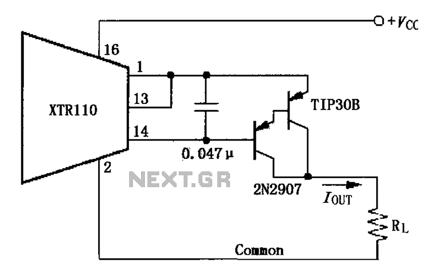
The circuit consists of two discrete PNP Darlington transistors that form the external PNP transistor QEXT circuit to enhance output current. The use of integrated Darlington transistors is not recommended, as the internal base-emitter resistor can introduce additional errors....
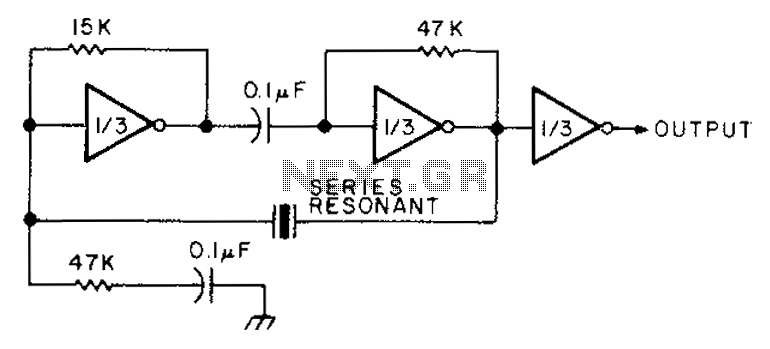
The circuit diagram illustrates the connection of all three components of the series resonant crystal and triple CD4049 inverter. The supply voltage range is between 3 to 15 volts, making it suitable for various applications. This design is compact...