
12V to 3V Car adapter

The LT1074CT briskly switches the supply voltage on and off in response to the signal applied to its F/B input, to the extent that the average output voltage is at the required level. The values of potential divider resistors R1-R3 have been chosen to attenuate the output voltage so that there is 2.5 V at the F/B pin. The difference between the attenuated output voltage and the internal 2.5-V reference is used to control the modulation effect of the switcher.
Components R2 and C2 provide frequency stabilization for the feedback loop. Inductor L1 along with the LT1074CT form the main switching components, while C1 provides decoupling for the output load. The 3-V output voltage is taken from screw terminal J1. With this circuit built, boxed up and installed in your car, you can look forward to possibly your first ‘quiet’ long car journey.
The LT1074CT is a versatile step-down switching regulator that efficiently converts higher voltages to lower voltages, making it ideal for powering low-voltage devices from a car's electrical system. The input voltage range accommodates the typical automotive environment, which can vary from approximately 10.5 volts to 14.5 volts, depending on the vehicle's charging system.
The circuit's design includes essential components for stability and reliability. The use of a fused cigarette lighter plug is crucial for safety, protecting the circuit from potential overcurrent conditions. The diode D2 serves as a safeguard against reverse polarity, ensuring that the circuit components are not damaged if the power supply is connected incorrectly.
In the feedback loop, the resistors R1, R2, and R3 are carefully selected to set the output voltage to 3 volts. The LT1074CT's feedback mechanism compares the divided output voltage to its internal reference voltage, adjusting the duty cycle of the switching signal to maintain a stable output. Capacitor C2, in conjunction with R2, forms a compensating network that helps stabilize the feedback loop against oscillations, which can be crucial for maintaining output voltage stability under varying load conditions.
Inductor L1 is a key component in the energy transfer process, storing energy when the switch inside the LT1074CT is closed and releasing it to the output when the switch opens. The output capacitor C1 smooths the voltage at the output terminal J1, ensuring that the connected devices receive a clean and stable 3-volt supply, which is particularly important for sensitive electronics like personal hi-fi systems and handheld gaming devices.
This circuit design not only addresses the power requirements of low-voltage devices but also considers the operational environment of a vehicle, ensuring that it can function reliably during long journeys. The overall configuration promotes efficient power conversion with minimal noise, making it suitable for use in a car where noise levels can be a concern.This 3 volts Car Adapter circuit is based on a standard LT1074CT switching regulator IC. The schematic shows the LT1074CT used as a positive step-down or ‘buck’ converter. The ‘switcher’ is used to convert a +12-volt car battery voltage down to +3 volts for use with the personal hi-fi’s and handheld games for the author’s two boisterous children on long car journeys. Note at under ten years of age, children will rarely be hi-fi aficionado’s and are generally not concerned with any noise generated by the ‘switcher ‘circuit.
The circuit is connected to the car +12-V system via the cigarette lighter socket — is advisable to use a fused version of the cigarette lighter plug. The +12-V arrives on the board via screw- terminal block J2. Diode D2 provides a reverse voltage protection, while C3 decouples the input to the switcher IC. The LT1074CT briskly switches the supply voltage on and off in response to the signal applied to its F/B input, to the extent that the average output voltage is at the required level.
The values of potential divider resistors R1-R3 have been chosen to attenuate the output voltage so that there is 2.5 V at the F/B pin. The difference between the attenuated output voltage and the internal 2.5-V reference is used to control the modulation effect of the switcher.
Components R2 and C2 provide frequency stabilisation for the feedback loop. Inductor L1 along with the LT1074CT form the main switching components, while C1 provides decoupling for the output load. The 3-V output voltage is taken from screw terminal J1. With this circuit built, boxed up and installed in your car, you can look forward to possibly your first ‘quiet’ long car journey.
🔗 External reference
Related Circuits
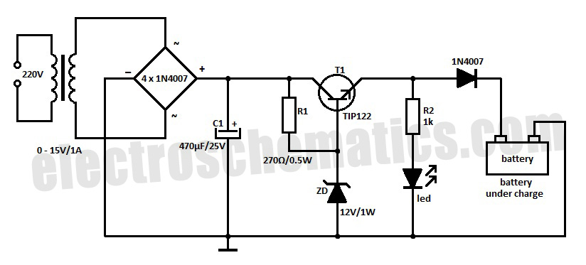
This circuit can automatically and efficiently charge 6V and 12V batteries. A key factor in the successful operation of the circuit is the use of a high-quality transformer [T1] that has excellent insulation and resistance to short circuits. The circuit...
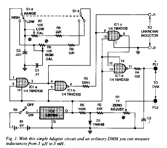
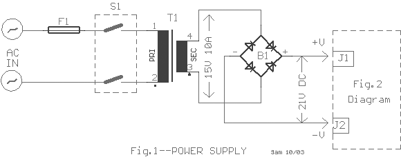
An inductance meter can be a valuable test instrument for hobbyists. However, few people own them due to their high price. The Inductance Meter Adapter described in this article is a circuit that, when connected to a digital multimeter...
Most battery chargers lack provisions for current and voltage regulation. The step-down voltage is primarily utilized for charging purposes. Many battery chargers operate on a straightforward principle of reducing the input voltage to a level suitable for charging a battery....

This circuit switch slowly on and off the internal lights in a car. The delaying time can be adjusted changing the values of the 10k, 4M7 resistors and capacitor. More: The BUZ74 can handle voltages of 500V, but you...
This project is currently under construction and has not been validated for functionality. A signal generator, resistor, and oscilloscope were utilized to measure the value of an inductor for a battery charger project. In the search for an affordable...
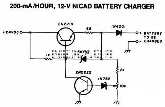
The following diagram is the schematic diagram of a 12V NiCAD battery charger with a charging rate of 200mA per hour. This NiCAD battery charger circuit charges the battery at 75 mA until the battery is fully charged, after...