
200mA/Hour & 12V NiCAD Battery Charger

The 12V NiCAD battery charger circuit is designed to efficiently charge nickel-cadmium (NiCAD) batteries while ensuring proper management of the charging process to extend battery life. The circuit typically includes a transformer, rectifier, voltage regulator, and current limiting components.
The transformer steps down the mains voltage to a suitable level for charging the 12V NiCAD battery. The rectifier converts the AC voltage from the transformer into pulsating DC voltage. A smoothing capacitor may be included to reduce the ripple in the DC output, providing a more stable voltage to the battery.
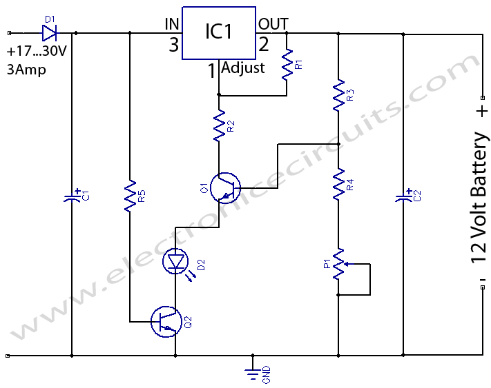
Current limiting is achieved through a resistor or a more sophisticated current regulator circuit, which initially allows a charging current of 75 mA. This initial charging phase is crucial for safely bringing the battery up to a full charge without overheating or damaging the cells. Once the battery reaches its full charge state, the circuit automatically reduces the current to a trickle charge, typically around 10% of the initial charging current, to maintain the battery's charge without overcharging.
Additional features may include a charge indicator LED to show when the charger is active and possibly a thermal cutoff or fuse for safety, preventing damage due to overheating. The overall design emphasizes reliability, efficiency, and safety, making it suitable for regular use in charging 12V NiCAD batteries.The following diagram is the schematic diagram of 12V NiCAD battery charger with charging rate of 200mA/Hour. This NiCAD battery charger circuit charges the battery at 75 mA until the battery is charged, then it reduces the current to a tri..
🔗 External reference
Related Circuits
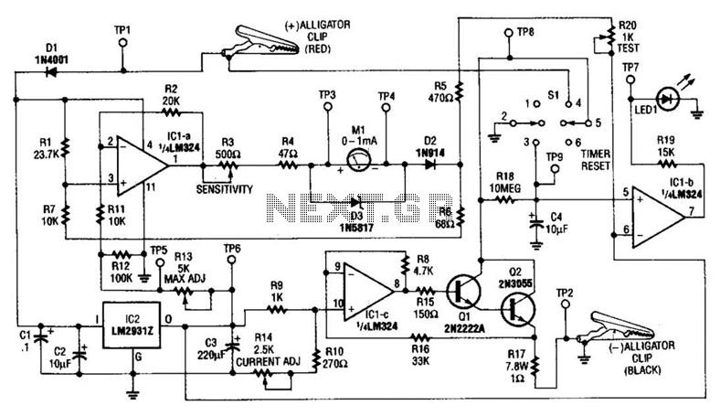
This circuit measures the cold cranking amps of a battery by discharging the surface charge and then assessing the internal resistance. This method provides a more accurate measurement than merely observing the instantaneous voltage drop under load. A constant-current...
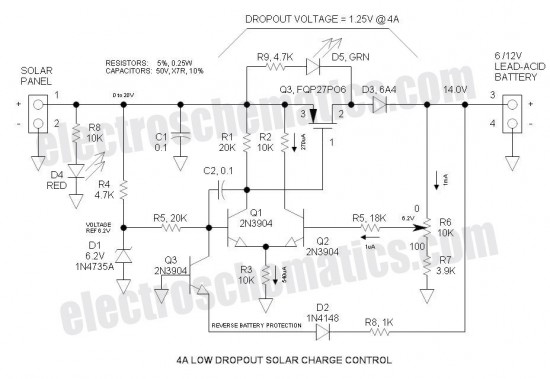
This Low Dropout Voltage (LDO) solar charge controller utilizes a straightforward differential amplifier combined with a series P-channel MOSFET linear regulator, creating an effective synergy. The voltage output is adjustable and is primarily designed for charging 12V lead-acid batteries....
Mobile phone battery chargers available in local markets can be quite expensive. The circuit presented here offers a low-cost alternative for charging cellular phone batteries or battery packs with a rating of 7.2 volts. This low-cost phone battery charger circuit...
The charger in this project is designed to charge two AA NiMH or NiCd cells of any capacity (as long as they are the same) at approximately 470mA. It will charge 700mAh NiCds in about 1.5 hours, 1500mAh NiMHs...
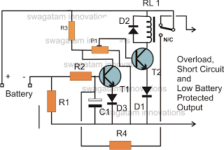
The battery voltage must pass through resistor R1 before reaching the output load. As a result, the current flowing through R1 is proportionately transformed into a voltage across it. When the battery voltage drops below a certain threshold, the...
12 Volts Lead Acid Battery Charger Circuit. Apart from serving as a standard battery charger, this circuit is ideal for providing a constant charge to a 12-Volt lead-acid battery. This 12-Volt lead-acid battery charger circuit is designed to efficiently charge...