
12v to +5V, -12V, +12V, +24V adaptor

The circuit described is a versatile voltage converter designed to derive multiple voltage levels from a 12V battery source. It is capable of providing both positive and negative output voltages, making it suitable for various electronic applications. The core of the design is an oscillator operating at approximately 7 kHz, which is established by the resistor R1 and capacitor C28. This oscillator drives a series of gates in the integrated circuit IC1 (74HC14), which are configured in parallel to ensure adequate current drive to the subsequent stages.
Transistors Q1 to Q4 (TIP31 and TIP32) serve as the primary switching elements, amplifying the oscillator signal to generate the necessary drive current for the voltage conversion process. The circuit employs a cascade configuration of diodes (D1 to D4 and D5 to D9) and capacitors (C14 to C17 for negative voltage and C19 to C23 for positive voltage) to rectify and filter the output, converting the AC-like signal from the oscillator into stable DC voltages.
Voltage regulation is achieved through the use of linear voltage regulators IC2 (7824 for +12V output) and IC3 (7912 for -12V output), which provide stable output voltages suitable for powering sensitive electronic components. Inductors L1 to L4 are strategically placed at the outputs of the regulators to suppress any residual oscillations, ensuring clean and stable voltage levels.
The current output capability of the circuit ranges between 100 mA to 200 mA, depending on the load and the specifications of the components used. The operational duration of the circuit is dependent on the capacity of the battery (greater than 3Ah), with longer durations achievable with higher capacity batteries. To manage heat dissipation, all transistors and voltage regulators are mounted on a heatsink, which is essential for maintaining operational stability and prolonging the lifespan of the components.
Part List
R1=6.8Kohms
C1-4-8-12-18=100nF 100V
C2=220uF 25V
C3-9-=680nF 63V
C5-11-26=4.7uF 16V
C6-7-10-27=47uF 25V
C14-15-16-17=220uF 25V
C19-20-21-22-23=220uF 25V
C28=3.3nF 63V
IC1=74HC14
IC2=7824
IC3=7912
D1....9=1N4001
Q1-3=TIP31
Q2-4=TIP32
BATT=BATTERY 12V >3Ah
L1-2=VK200
L3-4=560µH
L5=22µHMany times we needed a variety of voltages, from a battery 12V. With the circuit, we can take voltages smaller or bigger, positive or negative, from a battery 12V. The idea is based in oscillator roughly 7KHZ, round the R1, C28, that lead the remainder gates of IC1, that are connected at the parallel, (so that they provide the essential current of drive), that drive with the line their transistors Q1 until Q4. Then exist two circuits of "cascade" constituted from diodes and capacitors, D1 until D4, C14 until C17 for the negative and D5 until D9, C19 until C23 for the positive voltage, that drive the corresponding stabilizers.
In the outputs of stabilizers exist inductors, which they remove and the last remains of oscillation. The current that we can take from the outputs are order the 100 until 200 mA. The total time that will capacity of battery it gives the current that we want, it's up to from her capacity on Ah, as long as more so much more time. All the transistors and the stabilizers, good it is they are placed in a heatsink, in order to it remove the produced heat.
Part List R1=6.8Kohms C19-20-21-22-23=220uF 25V IC2=7912 C1-4-8-12-18=100nF 100V C13-24-25-29=100nF 100V IC3=7805 C2=220uF 25V C28=3.3nF 63V D1....9=1N4001 C3-9-=680nF 63V Q1-3=TIP31 BATT=BATTERY 12V >3Ah C5-11-26=4.7uF 16V Q2-4=TIP32 L1-2=VK200 C6-7-10-27=47uF 25V IC1=74HC14 L3-4=560?H C14-15-16-17=220uF 25V IC2=7824 L5=22?H 🔗 External reference
Related Circuits
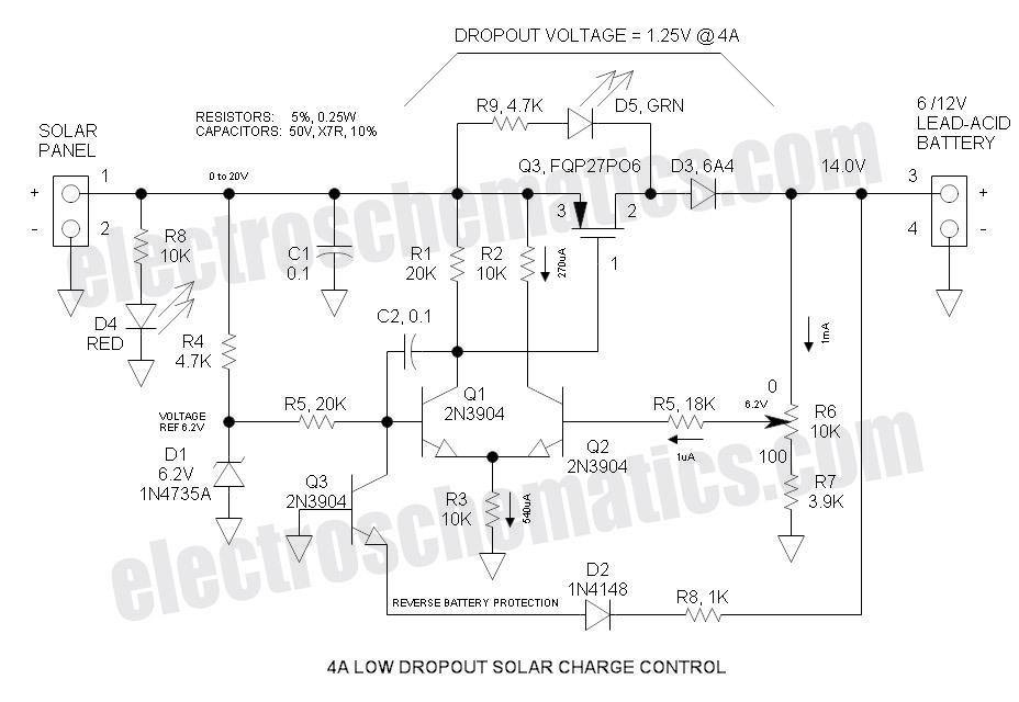
This Low Dropout Voltage (LDO) solar charge controller employs a differential amplifier and a series P-channel MOSFET linear regulator, which work exceptionally well together. The output voltage is adjustable and primarily designed for charging 12V lead-acid batteries. The input...
The objective is to add a security sensor light near the main entrance that operates on 12 volts. While 12-volt PIR sensors are available, they tend to be costly, often exceeding $50 each and are specifically designed for security...
The color of the LED makes a significant difference. The type and size of the LED, such as 3mm or 5mm, and the power source are crucial factors to consider. More information is required for accurate calculations. A basic...
This project is a cost-effective solution for operating 20 or 40-watt fluorescent tubes. The most efficient configuration utilizes a 40-watt tube or two 20-watt tubes connected in series. The circuit can be assembled using components sourced from a junk...
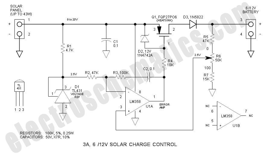
This solar charge controller integrates multiple features into a single design, including a 3A current rating, low dropout voltage (LDO), and a range of voltage adjustment capabilities. The solar charge controller is a critical component in solar energy systems, tasked...
This inverter circuit can provide up to 800mA of 12V power from a 6V supply. For example, you could run 12V car accessories in a 6V car. The circuit is simple, about 75% efficient and quite useful. By changing...