
12vac to 220vac inverter circuit

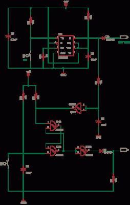
This inverter circuit utilizes a 555 timer IC in astable mode to produce a square wave signal, which is essential for driving the power transistors Q1 and Q2. The frequency adjustment through potentiometer R4 allows for fine-tuning of the output frequency, which is critical for applications requiring precise line frequency operation.
Transistors Q1 and Q2 serve as the amplification stage, switching the current through the primary winding of transformer T1. The transformer is configured such that its secondary winding provides the necessary voltage increase from 12V DC to 220V AC. The choice of transformer is crucial; a filament transformer is typically used due to its ability to handle the necessary power levels and provide the required turns ratio for voltage step-up.
Capacitor C4 and inductor L1 form a low-pass filter that smooths the output waveform. This filtering is vital to convert the square wave output from the transistors into a more sinusoidal waveform, which is generally required for most AC applications. The filter helps to reduce harmonic distortion, improving the quality of the AC output.
Careful selection of component values, particularly for the transformer and filter components, is essential for optimal performance of the inverter. The circuit design must ensure that the transformer can handle the expected load, and the filter components must be chosen to achieve the desired output characteristics while maintaining efficiency. This inverter circuit can be employed in various applications, including powering small appliances or serving as a backup power source.This simple 12VDC to 220VAC inverter circuit produces an AC output at line frequency and voltage. The 555 is configured as a low-frequency oscillator, tunable over the frequency range of 50 to 60 Hz by Frequency potentiometer R4. The 555 feeds its output (amplified by Q1 and Q2) to the input of transformerT1, a reverse-connected filament transformer with the necessary step-up turns ratio.
Capacitor C4 and coil L1 filter the input to T1, assuring that it is effectively a sine wave. Adjust the value of T1 to your voltage. 🔗 External reference
Related Circuits
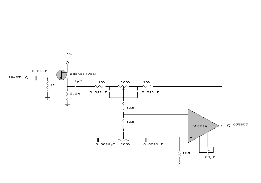
This circuit is a simple series tone control circuit. It utilizes the surgical amplifier LM301A. The JFET 2N3684 provides high input impedance and low noise for the unbuffered operational amplifier, which operates in an equalizer (EQ) configuration. Further details...
The circuits examined thus far rely on linear feedback for their operation. The magnitude of the signal returned to the negative input is always strictly proportional to the output voltage. Consequently, within the limits defined by the operational amplifier...

Building a signal generator is an essential project for any analog DIY enthusiast. While already possessing a bench signal generator, the intention was to create a compact, battery-powered device for quickly testing new effect designs. An enclosure from a...

Illuminate your tabletop with this stylish White LED Lamp. It is powered through a USB port, making it perfect for taking notes while browsing the internet. The USB port can provide a convenient power source. The White LED Lamp is...
This circuit is a simple -5V power supply using a 555 timer, designed for low-power analog applications involving FET operational amplifiers. The circuit converts +5V to -5V to create a dual power supply. It operates as a 555 astable...
NiCd battery charger schematic and description. This NiCd battery charger circuit can charge 12V, 6V, and 9V battery packs. The NiCd battery charger circuit is designed to efficiently charge nickel-cadmium (NiCd) batteries, specifically those with voltage ratings of 12V, 6V,...