
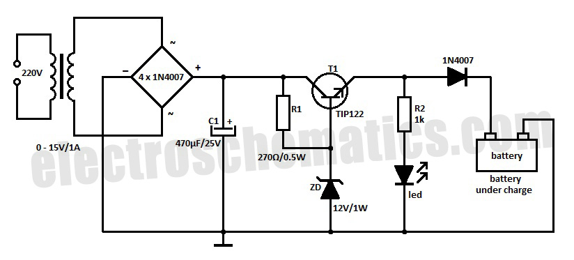
nicd battery charger circuit

The NiCd battery charger circuit is designed to efficiently charge nickel-cadmium (NiCd) batteries, specifically those with voltage ratings of 12V, 6V, and 9V. The circuit typically consists of a transformer, rectifier, voltage regulator, and additional components such as resistors and capacitors to ensure stable operation.
The transformer steps down the mains voltage to a suitable level for charging the batteries. After the transformer, a rectifier converts the alternating current (AC) to direct current (DC). The rectified output is then smoothed using capacitors to reduce voltage ripples, ensuring a more stable charging voltage.
A voltage regulator may be included to maintain the charging voltage at an appropriate level for the specific battery voltage being charged. This is crucial because overcharging can lead to battery damage and reduced lifespan. Additional components, such as diodes, may be employed to prevent reverse current flow, protecting the circuit and the batteries.
To accommodate different battery voltages, the circuit may feature selectable configurations or a variable resistor that allows the user to adjust the charging voltage as needed. Safety features, such as thermal protection and current limiting, are also essential to prevent overheating and overcurrent conditions during the charging process.
Overall, this NiCd battery charger circuit provides a reliable solution for charging various battery packs while ensuring safety and efficiency.Nicd battery charger schematic and description. This Nicd battery charger circuit can charge 12V, 6V, & 9V battery packs. .. 🔗 External reference
Related Circuits
Most battery chargers lack provisions for current and voltage regulation. The step-down voltage is primarily utilized for charging purposes. Many battery chargers operate on a straightforward principle of reducing the input voltage to a level suitable for charging a battery....
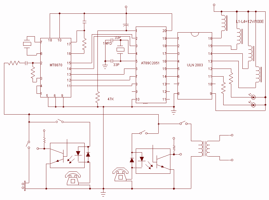
This project is used as an electronic private exchange. It has two telephones, which have the intercom facility, and they can be connected to the telephone line. All the functions are controlled by the 8-bit microcontroller AT89C2051 which has...
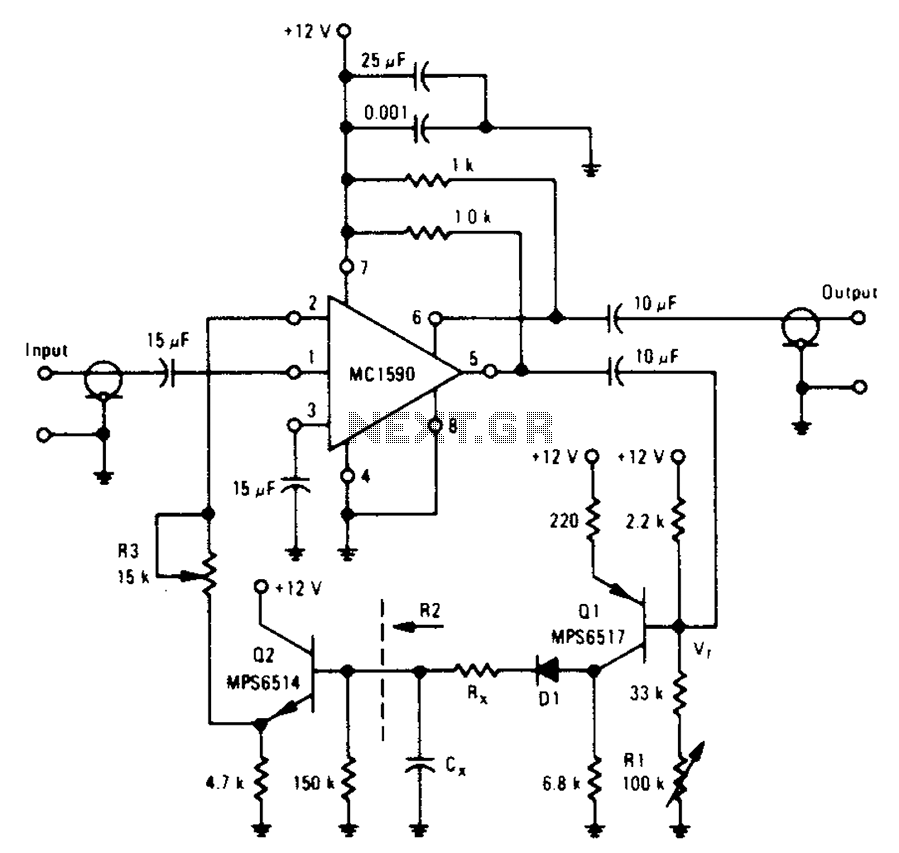
An amplifier designed to achieve a voltage gain of approximately 20, utilizing the MPS6517 PNP transistor in the emitter follower configuration. The RI controller allows for adjustment of the transistor's quiescent point. The output signal is activated only when...
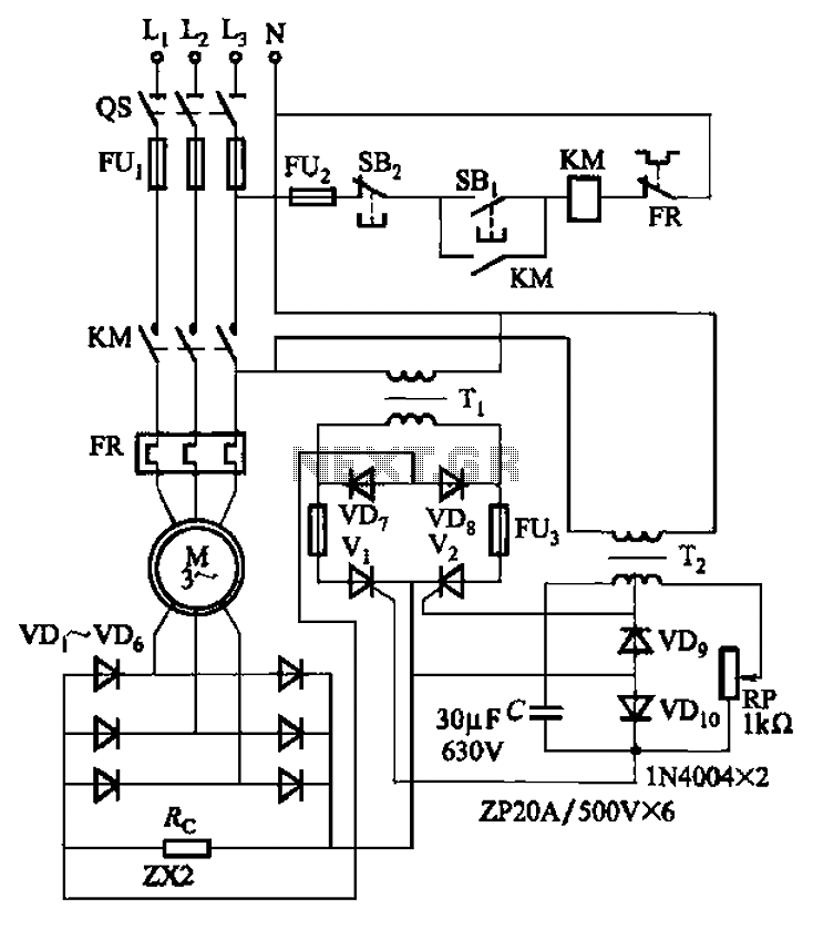
The circuit depicted in Figure 3-171 includes an auxiliary power supply that operates on single-phase AC power. It features a single-phase half-wave controlled bridge composed of diodes VD7, VD8, and thyristors V1, V2. The output current is managed by...
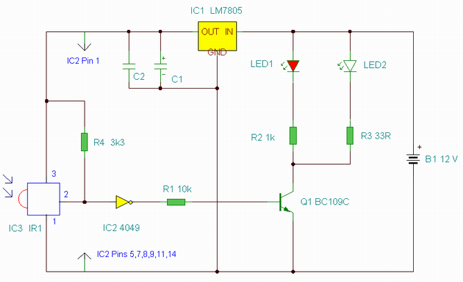
This is an enhanced infrared (IR) remote control extender circuit. It features high noise immunity, resistance to ambient and reflected light, and an increased operational range. The improved IR remote control extender circuit is designed to extend the range of...
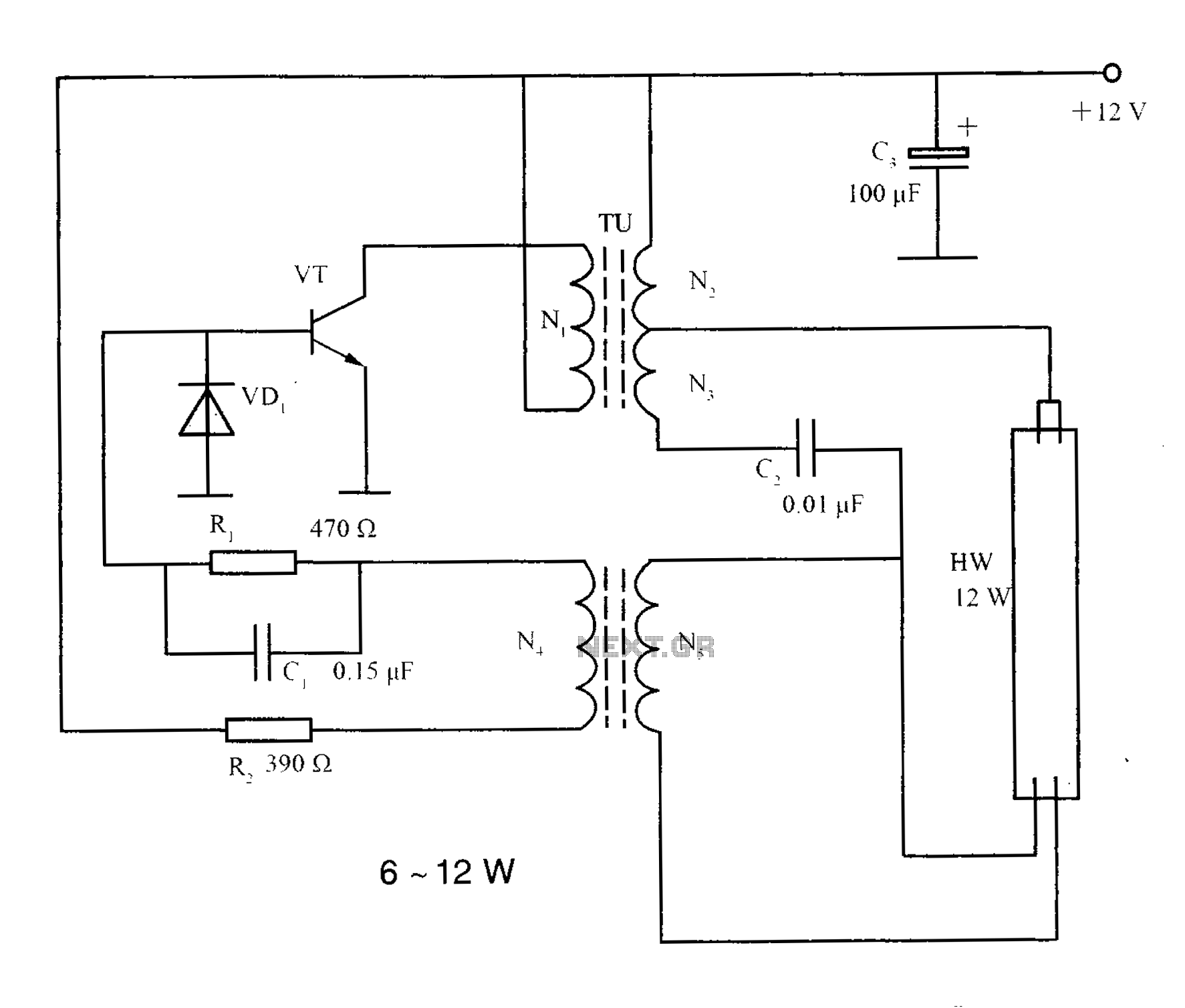
The lighting inverter circuit is designed for 6 to 12W fluorescent lamps. It operates by first bucking the mains voltage, followed by rectification and filtering to charge a battery. When the inverter is activated, it generates a high-frequency alternating...