
13KV High voltage power supply

The high-voltage power supply circuit is designed to convert low voltage input into high-voltage output through a series of components that work in conjunction. The inverter circuit, utilizing Q1, operates by switching the input voltage to create a pulsed output. This pulsed output is essential for driving the silicon-controlled rectifier (SCR1), which acts as a controlled switch that can handle high voltages and currents.
Capacitor C2 is employed to smooth the output voltage and provide energy storage, ensuring that the SCR operates efficiently during the switching process. The component labeled ?2 is critical as it steps up the voltage to 4.5 kV, which is then processed by the voltage-tripler network. This network typically consists of capacitors and diodes arranged to multiply the voltage, ultimately delivering a high output of 13.5 kV.
The inclusion of R1 as a current transformer allows for the integration of audio signals within the circuit, facilitating the control and modulation of the high-voltage output. The range of 3k to 500K indicates its versatility in handling different audio frequencies and signal levels.
L2, the flash tube trigger transformer, is specifically designed to generate a high-voltage pulse necessary for triggering flash tubes, which are commonly used in photography and other applications requiring intense bursts of light. With a secondary voltage of 6 kV, L2 ensures that the triggering mechanism operates effectively, providing the necessary energy to initiate the flash.
Overall, this high-voltage power supply circuit is a robust design that integrates various components to achieve high efficiency and performance in generating and controlling high-voltage outputs.This high-voltage power supply has an inverter around Q1 that supplies 150-V pulses to the converter of SCR1 and C2. The output of ?2 is a 4.5-kV pulse that is multiplied by the voltage-tripler network (right) to produce 13.5 kV.
R1 is a 3k to 500K CT transistor audio transforfiler, L2 is a flash tube trigger transformer with a 6-kV secondary.
Related Circuits
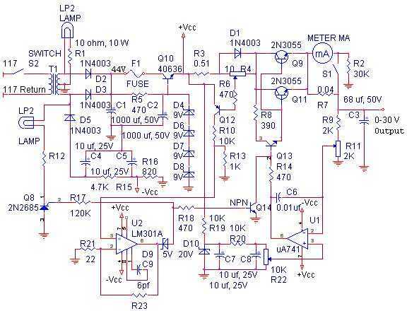
The linear power supply, shown in the schematic, provides 0-30 volts, at 1 amp, maximum, using a discrete transistor regulator with op-amp feedback to control the output voltage. The supply was constructed in 1975 and has a constant current...

This circuit design is for a high current toggle switch, adapted from the "Toggle Switch Debounced Pushbutton" by John Lundgren. It is intended for applications where the load needs to be switched on from one location and off from...
Current-controlled switching-mode power supplies (SMPS) are increasingly popular due to their ability to allow pulse-by-pulse current control and monitoring, enhancing reliability and robustness compared to voltage-controlled alternatives. Current control also removes a positive zero in certain transfer functions, contributing...
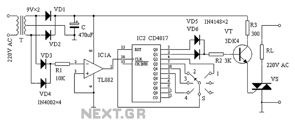
The zero-power regulator circuit is simple, reliable, and functional. It is suitable for various electric power adjustment applications, such as series-wound motor power adjustment. The operational principle of the circuit involves several components, including the power circuit, an AC...
This is a simple spanniningszoeker that is very suitable for car, for connection of alarm systems, handsfree kits, radios, etc. At rest, the yellow LED because the path of least resistance. If the probe with a positive or negative...
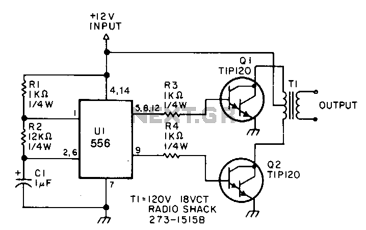
This low-power inverter utilizes only nine components to convert 10 to 16 VDC into a 60 Hz, 115 V square-wave output suitable for operating AC equipment with a maximum power of 25 W. The initial section of the 556...