
14 Volt Battery Charger Circuit Schematic Diagram

This circuit functions as a 14-volt battery charger, suitable for charging various types of batteries, particularly nickel-cadmium (NiCad) batteries and lead-acid accumulators. The design ensures that the output voltage is maintained at 14 volts, which is optimal for charging a 12-volt battery system. The maximum output current of 4A indicates that the charger can effectively charge batteries with a capacity of 4A or higher, making it versatile for different battery sizes.
The use of operational amplifiers such as the CA3140 or LM324 allows for precise regulation of the output voltage and current. These ICs can be configured in a feedback loop to maintain the desired output voltage, ensuring safe and efficient charging. The choice between the two ICs provides flexibility in design, allowing for the selection based on availability or specific performance characteristics.
The AC input voltage is first stepped down using a transformer, which reduces the voltage to a suitable level for charging. Following the transformer, a diode rectifier is employed to convert the AC voltage to DC. The diode must be selected to handle the maximum forward current of 4A, ensuring reliability and preventing damage during operation.
Overall, this circuit represents a reliable and efficient solution for charging 12-volt batteries, incorporating essential components for voltage regulation and current control, while ensuring compatibility with various battery types.This Circuit have output voltage 14 volt with current maximum 4A. Can be use on nicad battery and accu, wet and dry. But the accu must be 12 Volt and have current 4A or higher. The current fillter voltage build of IC CA3140 or LM324. You can which two IC. From the AC voltage will be lowered by trafo and rectified by diode. You can use diode up to 4A, this voltage to be supply for circuit. You are reading the Circuits of 14 Volt Battery Charger Circuit And this circuit permalink url it is 🔗 External reference
Related Circuits
This analog switch circuit is designed to switch an analog line on or off. It consists of two analog switches in integrated circuit (IC) form that are controlled by two pushbuttons. The described analog switch circuit utilizes two integrated analog...
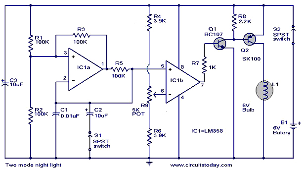
The operation and circuit diagram of a two-mode night light circuit are provided below. The two-mode night light circuit is designed to operate in two distinct lighting modes, typically offering a choice between a standard brightness setting and a dimmer,...
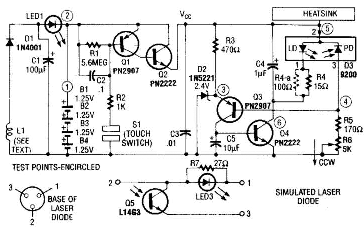
A laser diode TOLD9200 (Toshiba) serves as a source of laser light. Q3, Q2, and SI constitute a touch switch to control the laser. L1 is an RF pickup coil designed to extract energy from an RF-type battery charger....
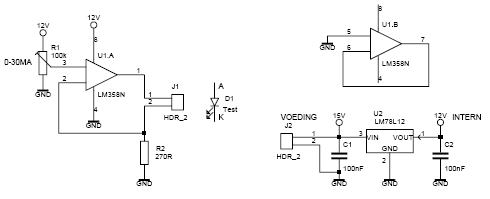
This led tester uses a power switched op-amp. The control range is about 0-30mA. Thus, all test and standard LEDs, the voltage across the LED to read. The power supply is an example lab power supply at least 15V,...
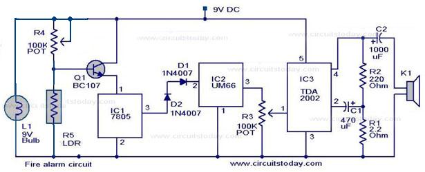
A simple fire alarm circuit utilizes a light-dependent resistor (LDR) and a lamp for smoke detection. The system operates by detecting smoke generated during a fire. An audible alarm is triggered when smoke is present. In the absence of...
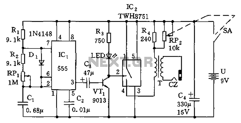
The circuit is composed of a 555 oscillator and an amplifier driver stage. It includes the 555 timer along with resistors R1, R2, RP1, capacitor C1, and other components forming a multi-harmonic oscillator. The frequency can be adjusted using...