
Analog Line Switch Circuit

The described analog switch circuit utilizes two integrated analog switches to manage the connection of an analog signal line. The operation of the circuit is straightforward: when a pushbutton is pressed, it activates one of the switches, allowing the analog signal to pass through, effectively turning the line on. Conversely, releasing the button deactivates the switch, cutting off the signal and turning the line off.
Each analog switch is typically implemented using CMOS technology, which provides low on-resistance and minimal signal distortion. The pushbuttons serve as the control interface, providing a simple user interaction to toggle the state of the switches. The circuit can be powered by a standard voltage supply, often in the range of 5V to 15V, depending on the specifications of the chosen analog switch IC.
In terms of layout, the circuit should ensure that the analog signal paths are kept short to minimize capacitance and interference. Proper decoupling capacitors should be placed close to the power supply pins of the IC to stabilize the voltage and filter out any noise that may affect the performance of the analog switches. The design may also include pull-down resistors on the pushbutton inputs to prevent floating states when the buttons are not pressed.
Overall, this analog switch circuit is suitable for applications where simple control of analog signals is required, such as in audio systems, signal routing, and other electronic devices that necessitate switching capabilities without significant signal degradation.This analog switch circuit is designed to switch on or off and analog line. it consists of two analog switches in IC form that are controlled by two pushbu.. 🔗 External reference
Related Circuits

The all-analog circuit presented controls the rate at which a miniature turbojet engine can be throttled. Increasing or decreasing the throttle too quickly on a miniature turbojet engine, or any jet engine, can lead to quick failure in flight,...

The Door Buzzer circuit utilizes an IC 555 to generate a sound resembling an electric bell. When the switch S1 is pressed, a loud sound is produced. This circuit is designed to be simple and requires minimal components. It...
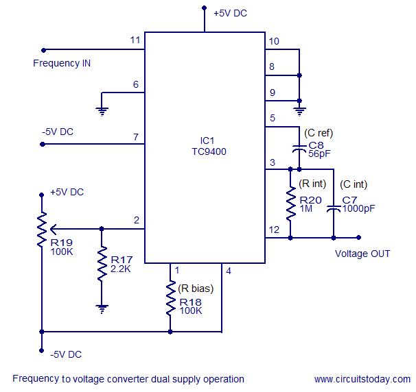
A simple frequency to voltage converter circuit designed around the TC9400 F to V / V to F converter IC. Dual and single supply versions are provided. The TC9400 is a versatile integrated circuit that converts frequency signals into corresponding...
The 8-pin 555 timer is one of the most versatile integrated circuits (ICs) available, utilized in numerous projects. With minimal external components, it can be employed to construct various circuits, many of which do not pertain to timing applications....

The primary component utilized is the ACS712 sensor from Allegro MicroSystems, designed for measuring current. It offers cost-effective and accurate solutions for AC or DC current sensing in industrial, commercial, and communication systems. A precise, low-offset, linear Hall sensor...

Have you ever observed the stairs to an upper story in your house transform into a waterfall? Or perhaps you returned home to find your aquarium fish attempting to swim across the carpet? For your sake, it is hoped...