
14 Watt Audio Amplifier

The audio amplifier circuit described is a robust design that effectively delivers 14 watts of output power, with the capability of increasing this output through higher power supply voltages. The amplifier's architecture is based on a discrete power operational amplifier, which is known for its reliability and low distortion characteristics. The circuit's gain configuration is determined by the resistor values R18 and R23, allowing for fine-tuning of the amplification factor.
The preamplifier stage of the circuit provides a voltage gain of 10, which, when combined with the power amplifier's gain, results in an overall gain of approximately 150. This significant amplification ensures that the audio signal is adequately boosted for driving speakers or other audio loads. Attention to component selection is crucial; for instance, the use of non-polarized capacitors for C2 and C9 is recommended. This choice helps maintain the integrity of the audio signal, especially in the context of frequency response and distortion.
The design also incorporates bass and treble controls, providing users with the ability to tailor the audio output to their preferences. This feature enhances the versatility of the amplifier, making it suitable for a variety of audio applications. The circuit's insensitivity to component variations further adds to its reliability, allowing for a range of components to be used without significantly affecting performance. Overall, this amplifier design represents a well-thought-out approach to audio amplification, combining simplicity, efficiency, and high-quality sound reproduction.The audio amplifier shown below provides 14 watts of power, but can provide much more simply by increasing the power supply voltage. This amp was built in 1975 and has worked reliably ever since. The power amp portion was published in Popular Electronics in the mid-1975s. I added a preamp and bass and treble controls. This amp has extremely low distortion and is relatively insensitive to the choice of components. The power amplifier is actually a discrete power op-amp. As such the gain is set by R18/R23. The pre-amp has a voltage gain of 10, for an overall gain of approximately 150. I recommend non-polarized capacitors for C2 and C9, even though the schematic show 🔗 External reference
Related Circuits
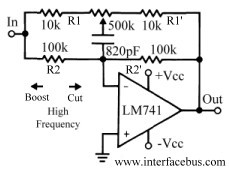
This discussion continues from the audio tone control topic, which introduced both passive and active tone controls. The follow-up topics may include a 2-Band Active Tone Control or a 3-Band Active Tone Control. An audio equalizer is utilized to...
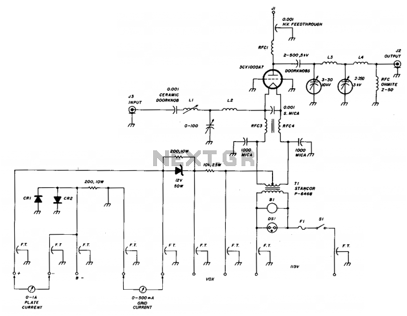
The amplifier utilizes a grounded grid circuit featuring either the Eimac 3CX1000A7 or 8877 ceramic/metal triodes designed for linear operation within the HF and VHF frequency ranges. It delivers a legal power output of 1500 watts PEP and continuous...
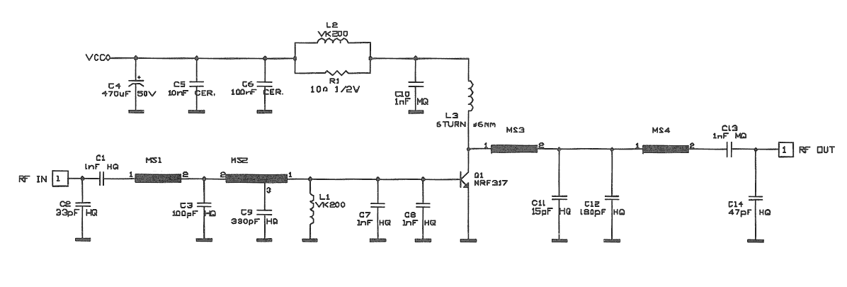
This amplifier is designed for TV transposers and transmitters. It incorporates microstrip technology and discrete linear push-pull transistors with gold metallization and diffused emitter ballast resistors to enhance ruggedness and reliability. The unit is fully assembled and tested with...
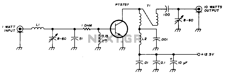
This 10-watt, 144-MHz power amplifier utilizes a TRW PT5757 transistor. The inductor LI consists of 4 turns of no. 20 enameled wire with a 3/32" inner diameter, while inductor L2 comprises 10 turns of no. 20 enameled wire with...
A friend purchased a relatively new Fender 60W combo amplifier for £5 from an acquaintance. The previous owner had taken it to three different repair shops, where it was deemed not worth repairing. Prior to receiving the amplifier, it...
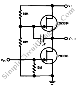
This is a simple high-gain JFET audio amplifier circuit. This circuit requires very low power but provides a high-gain amplification function. It is also referred to as JFET. The JFET (Junction Field Effect Transistor) audio amplifier circuit is designed to...