
14 Watt Compact Fluorescent Electronic Ballast
The circuit operates as an oscillator, utilizing a feedback mechanism between the transformer windings and the transistors to create a self-sustaining oscillation. The initial charging of the capacitors is critical for the operation, as it sets the conditions for the DIAC to trigger and subsequently activate Q2. The role of the inductors, particularly L1 and L2, is vital in controlling the current and providing the necessary inductive kick to sustain the oscillation. The small size of the components allows for a compact design, which is advantageous in applications where space is limited. The ferrite materials used for the inductors and transformer contribute to efficient magnetic coupling, minimizing losses and enhancing performance.
In practical applications, the circuit can be modified to accommodate different fluorescent bulb types, provided they operate within similar power ratings. The design's flexibility allows for adjustments in component values to optimize performance based on specific requirements. Careful consideration should be given to the heat dissipation of the components, especially the resistors and filaments, to ensure reliability and longevity of the circuit. Overall, this circuit exemplifies an efficient design for fluorescent lighting applications, showcasing the principles of oscillator circuits and transformer action in a compact form factor.This circuit came from a 14 Watt Commercial Electric spiral bulb from Home Depot. In fact, I drew it in that way because it was layed out very well, so much credit should go to Sam Goldwasser. It is a rather interesting oscillator circuit which I will attempt to explain the operation of. However, I don`t fully understand it, so if someone else doe s please contact me at the above e-Mail address so that the aspiring electronics experimenters who visit these pages may expand their understanding. On the other hand, if I got it right, also please tell me, or if you have anything to add to the explanation.
As the power comes in, it is filtered by L1 and a. 1uF capacitor. A. 47 Ohm reisitor is also provided and is probably fusible. It is then rectified by the bridge formed by D1-D4 and filtered by a 10uF capacitor. As power is first applied, a 100nF 63V capacitor begins charging through a 470k reisitor. Once this capacitor reaches 32V, the DIAC breaks over turning on Q2. Power then flows through Q2, the top winding of T1, L2, a filament of fluorescent bulb FL1, a 4. 7nF capacitor, the other filament of FL1, and a. 1uF capacitor, current being limited by L2 and the resistance in the filaments. Transformer action also begins inducing power in the other 2 windings of T1. This tends to begin to turn on Q1 and turn off Q2. Once Q1 is on, the charge that has built up in the. 1uF and 4. 7nF capacitors attached to FL1 begins flowing back the other way through the filaments, L2, the top turn of T1 and Q1. This once again induces power into the other two windings of T1 except in the opposite direction, eventually turning off Q1 and turning on Q2.
The 470pF capacitor and other 470k resistor apparently make sure that both transistors are not on at the same time. Otherwise, it would be a dead short! Once the arc starts, most of the current flows directly between the filaments instead of through them.
Only a small amount flows through them to keep them warm. All of the inductors and T1 are very small ferrites. In fact, the entire circuit is only 1 3/8" across. Everything is packed in and the filter capacitor is actually raised from the board by its leads to make space for other components underneath. L1 is 85 turns of 25-30AWG magnet wire on a round I shaped ferrite core. The core is 2mm in diameter and the top and bottom are 5mm diameter with 4mm in beteween where the coil is wound.
L2 is 150 turns of 25-30AWG magnet wire on an E core with a 1mm gap precut in the center leg of one of the halves. The center leg measures 6 x 2. 5mm in thicknesss. The outer legs measure 6 x 2mm. When the halves are put together, they are 13mm wide and 12mm tall. T1 is a tiny ferrite torroid with a 3mm hole, 6mm total diameter and is 3mm thick. Each of the 3 windings are 3 turns, counted in the usual way by the number of times the wire passes through the hole.
The circuit can be reused to successfullly power a T18 18" straight fluorescent bulb when your original spiral bulb goes. It should work with any fluorescent light that`s around 14 watts and produces an arc around 18" long.
In operation, the ballast seems to make one of the filaments run hotter than the other. This would seem to explain the failure mode of the original bulb because it had a bad filament. My bulb only lasted 3 years instead of the advertised 7. This could be from a DC component to the waveform. A simple check with an oscilloscope would verify this. Some of the other bulbs in the same fixtures are still going, so this problem seems to plague some and not others. Yes, very good to hear from you Mr. Ali. A good start would be to double the resistances and make sure your capacitors are up to the task. Just remember that when you rectify an AC sine wave that you will get 1. 414 times the RMS voltage which in your case will be around 311. 08V. To be safe, they should be at least 400V except the 100n which doesn`t need to be changed. The s 🔗 External reference
Related Circuits
This simple electronic buzzer circuit is based on a timer that operates to generate sound frequencies. The NE555 integrated circuit is utilized as an astable multivibrator, functioning at approximately 1 kHz to produce sound when powered on. The frequency...
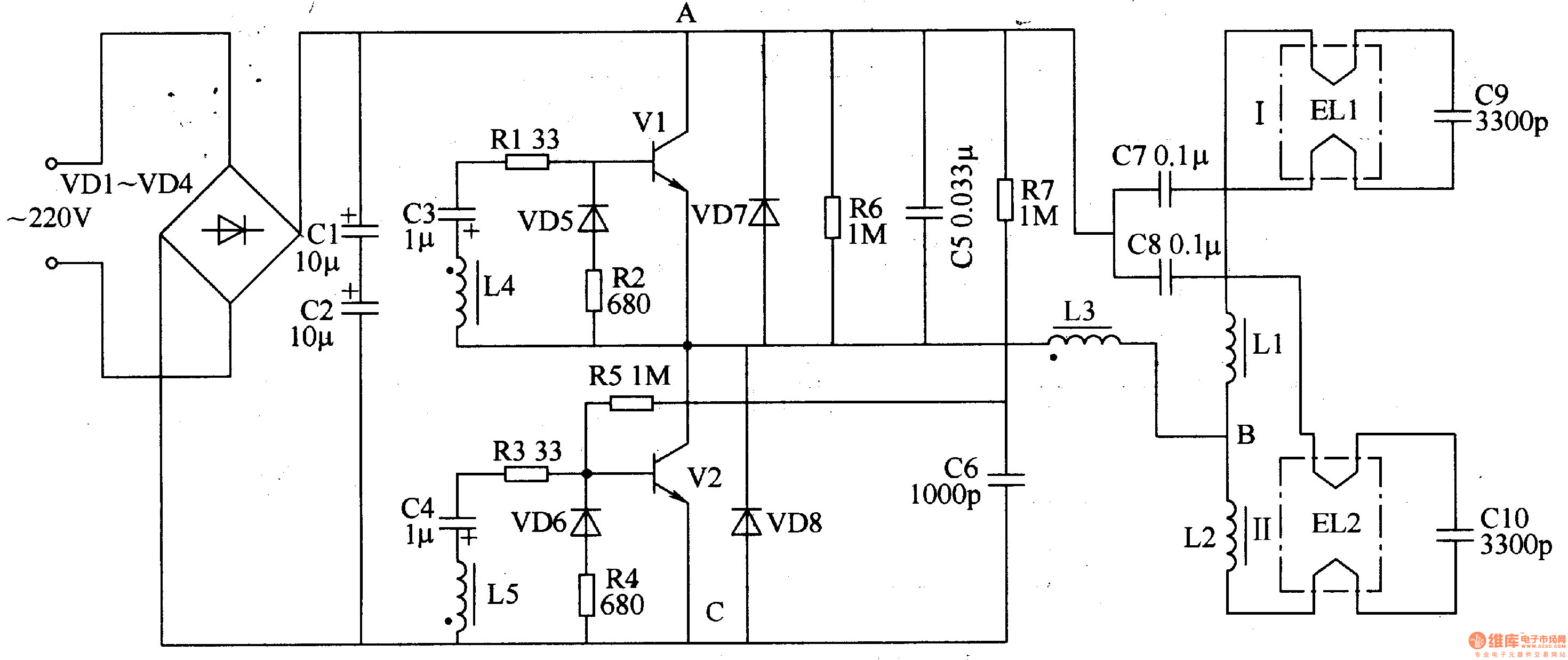
The electronic ballast circuit for fluorescent lamps comprises a rectifier filter circuit, a high-frequency oscillator circuit, and an output circuit, as illustrated in Figure 3-202. The rectifier filter circuit consists of rectifier diodes VD1-VD4 and filter capacitors C1 and...

There are many digital thermometers with ±1°C displays, but their accuracy is approximately ±1°C and they cannot be calibrated. A thermometer circuit was created using components available at a local electronics hobby shop, providing an educational experience. For a...

The schematic illustrates the design of a circuit that measures the resistance of the skin and transforms it into a functional switching signal. This circuit typically employs a resistive sensor, often referred to as a skin resistance sensor or galvanic...

A simple 16-volt switching power supply circuit can be constructed using the provided diagram, which is based on the MAX668 constant-frequency, pulse-width modulating (PWM), current-mode DC-DC controller. This integrated circuit is designed for a wide range of DC-DC conversion...
Currently, a basic MOSFET amplifier or power amplifier is designed to deliver an output power of ±100 Watts RMS with an 8 Ohm load, or ±160 Watts RMS with a 4 Ohm load. The simplicity of this circuit results...