
Fluorescent lamp electronic ballast

The electronic ballast circuit serves a crucial role in the operation of fluorescent lamps by regulating the electrical current and providing the necessary voltage to start and sustain the lamp's illumination. The rectifier filter circuit converts the incoming AC voltage to a stable DC voltage using diodes VD1 to VD4. These diodes are configured in a bridge rectifier arrangement, ensuring that the current flows in a single direction, which is essential for the subsequent filtering stage. The filter capacitors C1 and C2 smooth out the pulsating DC voltage, providing a more stable output that is suitable for the oscillator circuit.
The high-frequency oscillator circuit is vital for driving the fluorescent lamp. It typically operates at frequencies ranging from 20 kHz to several hundred kHz, which helps in reducing flicker and enhancing the efficiency of the lamp. Transistors V1 and V2 act as the main switching elements in this circuit. Their operation is controlled by the resistors R1-R7 and the capacitors connected to them, which help set the frequency and duty cycle of the oscillation. This oscillation generates high-frequency AC voltage that is necessary for the lamp's operation.
The output circuit of the ballast connects to the fluorescent lamp, providing the high-frequency AC voltage required to ignite and maintain the lamp's light output. The design of this circuit is critical as it must handle the voltage and current demands of the lamp while ensuring stability and efficiency. Overall, the electronic ballast circuit is a sophisticated assembly that integrates various components to enhance the performance and reliability of fluorescent lighting systems.The fluorescent lamp electronic ballast circuit is composed of the rectifier filter circuit, high-frequency oscillator circuit and output circuit, and it is shown in Figure 3-202. Rectifier filter circuitis composed of the rectifier diodes VDl-VD4 and filter capacitors Cl, C2. High-frequency oscillator consists of the transistors VI, V2, resistors Rl-R7, cap.. 🔗 External reference
Related Circuits
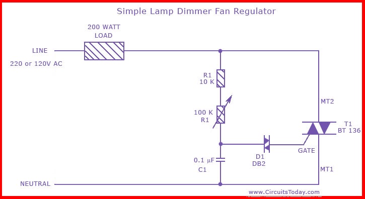
This is the circuit diagram of the simplest lamp dimmer or fan regulator. The circuit is based on the principle of power control using a Triac. The circuit operates by varying the firing angle of the Triac, which is...

The electronic doorbell circuit consists of a pickup amplifier, a monostable trigger circuit, a pulse counter circuit, a music generating circuit, an audio amplifier circuit, and additional components. The pickup amplifier circuit is composed of a piezoelectric ceramic element,...
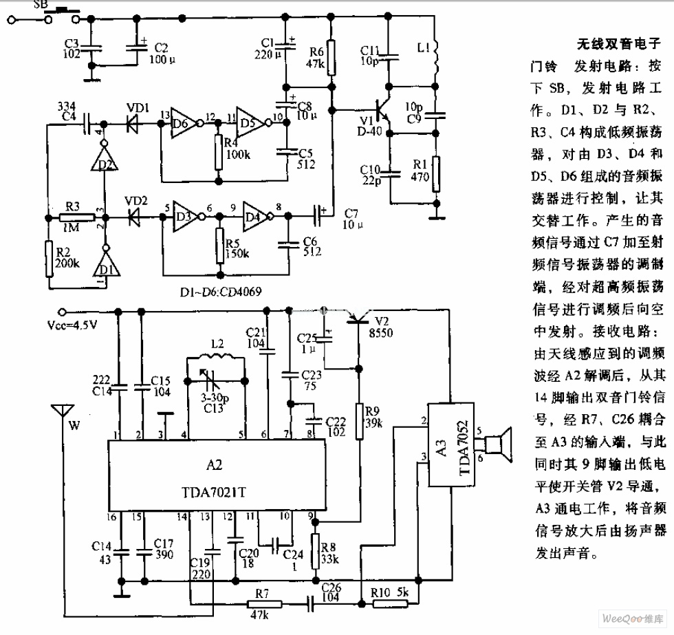
The transmitter circuit is activated by pressing the SB button. Components D1, D2, R2, R3, and C4 form a low-frequency oscillator that controls an audio oscillator made up of D3, D4, D5, and D6, allowing them to operate alternately....
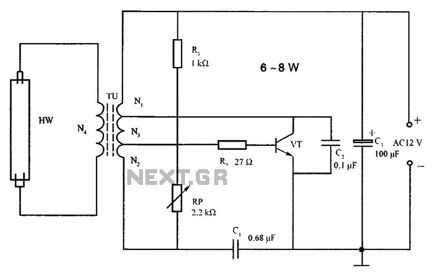
The lighting inverter circuit is designed for 6 to 8W fluorescent tubes. This circuit is appropriate for powering fluorescent tube circuits within the specified wattage. The parameters for the circuit are indicated in the accompanying figure. When utilizing a...
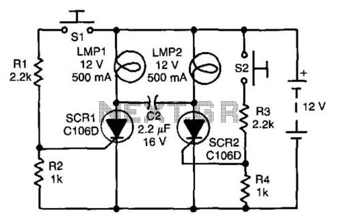
Assume first that SCR1 is on and SCR2 is off, allowing capacitor CI to be fully charged, with its LMP2 end positive. The state of the circuit can be altered by pressing switch S2. When SCR2 turns on, it...

The electronic watchdog circuit functions similarly to a traditional guard dog, monitoring a 10-meter area around a door. When someone enters this monitored zone, the circuit emits a realistic barking sound. This sound can be sustained for 10 seconds,...