
140W amateur radio linear amplifier 2-30Mhz

The amplifier circuit is designed to efficiently amplify RF signals, making it suitable for various applications, including communication systems and signal processing. The MRF454 devices are known for their high efficiency and reliability, which contributes to the overall performance of the amplifier.
The design typically includes a few critical components: the two MRF454 transistors, biasing resistors, coupling capacitors, and a power supply decoupling network. The transistors are arranged in a push-pull configuration to maximize power output and improve linearity. The input drive of 5 W is fed into the base of the transistors through coupling capacitors, which block DC voltage while allowing AC signals to pass.
The output stage of the amplifier is designed to deliver 80 W of power, ensuring that the amplified signal maintains fidelity and strength. The circuit should also incorporate adequate heat sinking for the MRF454 devices to manage thermal dissipation effectively during operation.
Power supply considerations are crucial; a stable 12 V DC source is necessary to ensure consistent performance. Additional bypass capacitors may be included near the power supply connections to filter out any noise and provide a stable voltage to the amplifier during operation.
Overall, this amplifier circuit is a practical solution for those needing a cost-effective and efficient amplification system, leveraging the capabilities of the MRF454 transistors to achieve the desired performance specifications.This inexpensive, easy to construct amplifier uses two MRF454 devices Specified at 80 W power output with 5 W of input drive, 30 MHz, ana 12 Vdc.
Related Circuits
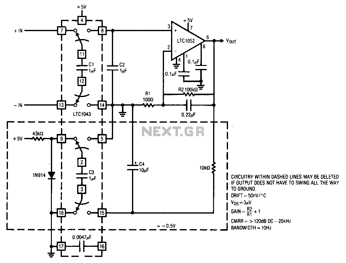
This circuit operates from a single 5 V power supply. The LTC1043 switched-capacitor instrumentation building block facilitates a differential-to-single-ended transition using a flying-capacitor technique. The circuit alternately samples the differential input signal and charges the ground-referred capacitor C2 with...
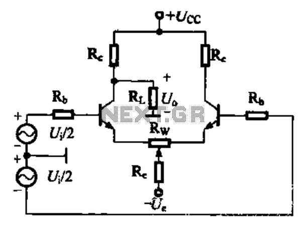
A comparison of four connection methods and features of a differential amplifier circuit is presented. The circuit demonstrates a magnification of a single tube with half the earnings, effectively countering common-mode negative feedback effects. The Common-Mode Rejection Ratio (CMRR)...
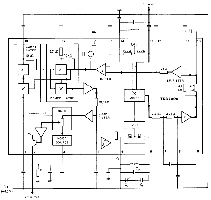
GENERAL DESCRIPTION The TDA7000 is a monolithic integrated circuit designed for mono FM portable radios or receivers, emphasizing minimal peripheral components to achieve compact dimensions and reduced costs. This integrated circuit features a Frequency-Locked-Loop (FLL) system with an intermediate...
The recommendation regarding the existing phono connector is to maintain its current configuration without making significant alterations. The procedure involves replacing the electrolytic and paper capacitors, adding a three-wire line cord, and utilizing the radio in its original state....
The circuit operates by utilizing a high-frequency section of the antenna to receive AM radio signals, amplifying radio-frequency signals at a selected vibration level of 465 kHz. The intermediate frequency (IF) signal is processed through an IF amplifier, followed...
The circuit design aims to create a preamplifier for television systems that operates within the UHF frequency range of 450 MHz to 800 MHz. The preamplifier circuit is essential for enhancing weak television signals before they are processed by the...