
TV Preamplifier via UHF Band

The preamplifier circuit is essential for enhancing weak television signals before they are processed by the main receiver. In the UHF frequency range of 450 MHz to 800 MHz, signals can be significantly attenuated due to various factors such as distance from the transmission tower and environmental obstructions. Therefore, an effective preamplifier must be designed to amplify these signals while minimizing noise and distortion.
The preamplifier typically includes a low-noise amplifier (LNA) stage, which is critical for maintaining signal integrity. The choice of components, such as transistors or operational amplifiers, is vital for achieving the desired gain and noise figure. For UHF applications, RF transistors like the BFP420 or low-noise operational amplifiers such as the AD8000 can be utilized.
The circuit should also incorporate impedance matching networks to ensure maximum power transfer from the antenna to the preamplifier. This can be achieved using LC networks or transformers designed for the specific frequency range. Proper filtering must be included to eliminate unwanted signals and harmonics, which can interfere with the desired UHF signals.
Power supply considerations are also crucial, as the preamplifier must operate efficiently across the specified frequency range. A regulated power supply circuit can be integrated to provide stable voltage levels, ensuring consistent performance.
In summary, the design of a UHF preamplifier circuit involves careful selection of components, consideration of impedance matching, filtering, and power supply management to effectively amplify weak television signals within the frequency range of 450 MHz to 800 MHz.The design of the circuit is aimed to create a preamplifier for television systems that would operate in the UHF frequency range of 450 MHz to 800 MHz and.. 🔗 External reference
Related Circuits
High-quality, discrete component design for input and tone control modules to complement the 60-watt MOSFET audio amplifier with a high-quality preamplifier design. The circuit design focuses on creating a high-fidelity audio preamplifier that enhances the performance of a 60-watt MOSFET...
This three-band equalizer circuit is an active filter network designed for bass, midrange, and high audio frequencies. It utilizes the LM833 operational amplifier from National Semiconductors. The output of this three-way graphic equalizer is intended to be DC coupled;...
In this project, you will make a simple 3-stage low-power broadcast-type circuit, using a crystal oscillator integrated circuit and a collector modulated AM oscillator with amplifier. You can connect the circuit to an electret microphone or amplified dynamic microphone....
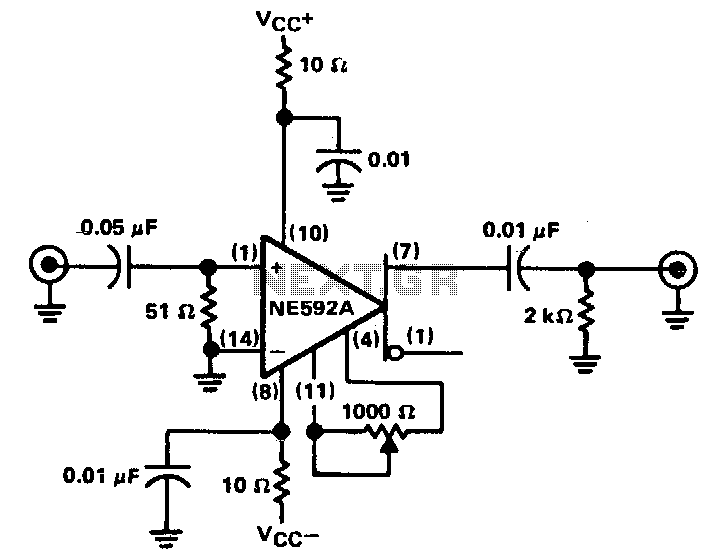
The circuit provides a voltage gain of 20 ±0.1 dB within a frequency range of 500 kHz to 50 MHz. The low-frequency response of the amplifier can be enhanced by increasing the value of the 0.05 µF capacitor connected...
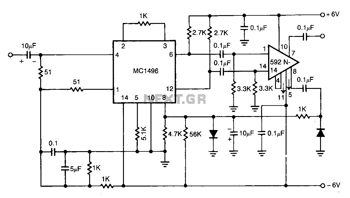
The NE592 is connected with the MC1496 balanced modulator to create an effective automatic gain control system. The signal is input to the MC1496 and then re-coupled to the NE592. Unbalancing the carrier input of the MC1496 allows the...
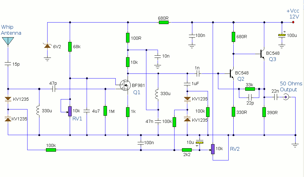
The antenna amplifier circuit comprises approximately 40 components, featuring two NPN transistors (BC548), one MOSFET (BF981), two varicap diodes (KV1235), and a 6.2V zener diode. It includes a 330µH inductor/coil, which can be modified for operation on different frequency...