
1488kHz signal generator and frequency divider circuit

The described circuit employs a quartz crystal resonator as a master oscillator, which is fundamental for generating stable frequencies. The 1488 kHz frequency serves as the primary reference point, enabling the division of this frequency into lower frequencies of 4 kHz, 12 kHz, and 124 kHz through a frequency divider circuit. This is achieved using various transistors, which are critical in amplifying and switching the signals within the circuit.
The transistors specified (3DG6C, 3CG3D, and 3DGl308) are essential for managing the current and voltage levels throughout the circuit. Their operational temperature ranges ensure reliability and performance stability under varying environmental conditions. The variable component, a pot-shaped ferrite, allows for tuning and adjustment of the circuit's inductance, which can be crucial for fine-tuning the output frequencies.
Inductors L1 and L3 are constructed from high-strength wire, providing the necessary inductance values for the circuit's operation. The number of turns in each inductor is carefully calculated to achieve the desired inductance, which interacts with the capacitive elements to set the resonant frequencies.
The use of SG8228 D-type CMOS flip-flops in the circuit provides a robust digital logic capability, enabling the creation of precise square wave outputs. Each flip-flop can be configured to perform various functions, such as frequency division and signal conditioning, essential for generating clean and stable outputs.
The 5G8058 type gates included in the design further enhance the logic capabilities of the circuit, allowing for various logical operations that can be implemented to control the flow of signals. The annotations provide additional details regarding the values and specifications of other components, ensuring that the circuit can be constructed with the necessary precision and reliability. Overall, this circuit design is well-suited for applications requiring precise frequency generation and signal processing.Used 1488kHz master oscillator quartz crystal resonator frequency stabilization, the output from the frequency divider dividing, obtained 4kHz, 12kHz, 124kHz three different square wave signal output. Circuit is shown. Transistor VTl, VT2, VT4, VT6: 3DG6C, = 50 ~ 85, VT3: 3CG3D, = 50 ~ 85, VT5: 3DGl308, = 65 ~ 115. Variables included T: using pot shaped ferrite, model MTT22F. Ll-2 µ0.35mm high strength wire, wound 36 turns. L3-4 µ0.31mm high strength wire, wound 21 turns. Al ~ A9: the SG8228 D-type CMOS, flip-flops, each integrated circuit with two D flip-flops components. Al0, All: 5G8058 type of door and integrated circuits, each circuit has two doors and components. Value of another element is shown in annotation, no special requirements.
Related Circuits
This is a 220V LED flasher circuit designed as a reliable alternative to thermally activated switches used for flashing Christmas tree lamps. It is a cost-effective and easy-to-assemble circuit. The components include R1 (100K), R2 (1K), R5 (1K), R3...
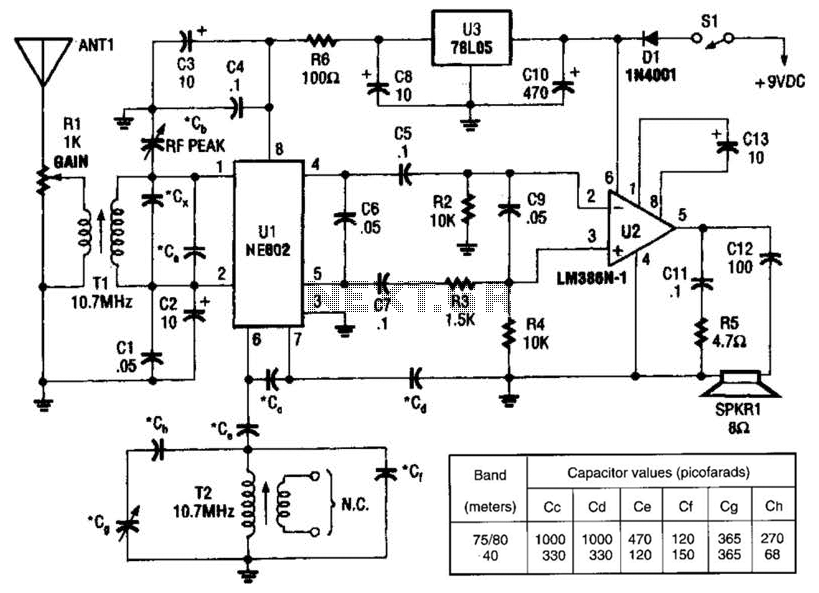
An NEC602 is utilized as a mixer with a zero intermediate frequency (IF) output, while U2 functions as an audio amplifier. This receiver is mainly designed for single sideband (SSB) and continuous wave (CW) signals. T1 and T2 are...
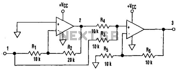
It is well understood that utilizing single-supply operational amplifiers (op amps) can present challenges when implementing simple functions in a bipolar signal environment. Often, this necessitates the use of additional op amps and other electronic components. Considering this, it...
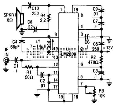
An LM2808 performs IF amplification of the 4.5-MHz sound subcarrier, limiting, detection, and audio amplification. If the center frequency must be changed, then change L1/C4. Audio output is 0.5 W. R3 is the volume control. The LM2808 is an integrated...
This circuit employs a protective resistor R2 along with a feedback resistor R1. Together, these components create a voltage divider that lowers the input voltage amplitude for IC1-a, ensuring that the protective diodes remain inactive. This arrangement enhances the...
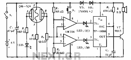
The QM-NJ9 is an alcohol sensor that detects the presence of alcohol by measuring the resistance values between points A and B. When alcohol is detected, the resistance decreases, leading to an increase in potential at point B. As...