
220V LED Flasher circuit diagram

The 220V LED flasher circuit operates by controlling the on-off flashing of LED lamps, making it suitable for decorative lighting applications, particularly during festive seasons. The circuit architecture consists of a combination of resistors, capacitors, diodes, and transistors that work in unison to create the desired flashing effect.
The resistors R1, R2, and R4 form a voltage divider and timing circuit with the capacitor C1, which determines the charging and discharging time, thus controlling the frequency of the flashing. The SCR (D5) is triggered by the transistors Q1 and Q2, which are configured in a manner that allows them to switch the SCR on and off based on the timing circuit's output. The choice of transistors, BC327 and BC337, provides sufficient current amplification to effectively drive the SCR.
For optimal performance, the values of C1 and R4 can be selected based on the desired flashing rate. Higher capacitance values lead to slower flashing rates, while lower capacitance values increase the flashing frequency. The circuit's design ensures that it can handle the low current requirements of LED lamps, which allows for the integration of smaller SCRs, thereby enhancing the circuit's overall efficiency and cost-effectiveness.
The inclusion of a female mains socket (SK1) allows for easy connection to the AC power supply, while the diodes (D1-D4) serve as rectifiers to protect the circuit from voltage spikes and reverse polarity, ensuring reliable operation. This LED flasher circuit exemplifies a simple yet effective solution for creating dynamic lighting effects in various applications.This is a 220V LED flasher circuit which is intended as a reliable replacement to thermally-activated switches used for Christmas tree lamp-flashing. This a cheap circuit and easy to build. R1_ 100K R2, R5_ 1K R3, R6_ 470R R4_ 12K C1_ 1000 F 25V D1-D4_ 1N4007 D5_ SCR P0102D Q1_ BC327 Q2_ BC337 SK1_ Female Mains socket The device formed by Q1, Q2 an
d related resistors triggers the SCR. The flashing frequency is provided by R1, R2 and C1. To change flashing frequency value, just set C1 value from 100 to 2200 F, don`t modify R1 and R2. Best performances are obtained with C1=470 or 1000 F and R4=12K or 10K. Due to low consumption of normal 10 or 20 lamp series-loops, very small and cheap SCR devices can be used, e. g. C106D1 or TICP106D. 🔗 External reference
Related Circuits
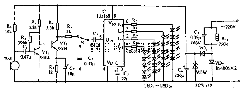
The circuit depicted in the figure involves the LD168, which functions as a sound level indicator for tape recorder speakers. It features four outputs capable of directly driving multiple light-emitting diodes. Additionally, the device can be activated by a...

Each time a pulse is applied to the control input for conversion, Q1 resets the 1000 pF capacitor to 0 V. This resetting action takes 200 ns, after which the capacitor begins to charge linearly. In precisely 10 microseconds,...

The purpose of this circuit is to animate shop windows using a capacitive sensor positioned behind a postcard-like banner. The card is placed against the glass inside the shop window, allowing visitors to activate the relay by placing their...

This circuit features a flashing LED that emulates the behavior of an incandescent lamp. The characteristic of an incandescent lamp is that it cannot abruptly change its brightness. The flashing LED circuit designed to mimic an incandescent lamp operates by...
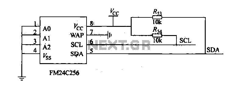
The FM24C256 is utilized as a slave interface circuit in an I2C bus configuration, with the address format specified in Table 27-3. The address pins A2, A1, and A0 are set to low; however, for extended storage capacity, adjustments...

The circuit is constructed using the ICM7217 integrated circuit from Intersil, which features a CMOS up/down counter with a four-digit display. The clock generator circuit, IC3, produces a square wave clock signal with a period of one second, available...