
1500 Watt RF Amplifier Circuit

The 1500 Watt RF Amplifier circuit is designed to amplify radio frequency signals, making it suitable for various applications in the field of telecommunications and microwave technology. This amplifier is capable of driving a transmitter antenna, ensuring that the RF signal is transmitted with sufficient power to reach the desired range.
The circuit typically consists of high-power transistors or RF power MOSFETs that are configured in a push-pull arrangement to enhance efficiency and linearity. The input stage of the amplifier may include impedance matching networks to optimize the power transfer from the source to the amplifier. This is crucial for minimizing signal reflections and maximizing output power.
The design may also incorporate a heat sink or cooling system, as high power levels can generate significant heat that must be dissipated to prevent damage to the components. Additionally, the amplifier circuit may include protection features such as over-temperature shutdown, over-current protection, and RF output monitoring to ensure reliable operation.
For microwave heating applications, the amplifier can be configured to operate at specific frequencies, allowing it to efficiently deliver energy to materials for heating purposes. This versatility makes the 1500 Watt RF Amplifier a valuable component in various industrial, scientific, and telecommunications applications.
Overall, the 1500 Watt RF Amplifier circuit represents a robust solution for high-power RF amplification, offering flexibility for a range of uses from driving antennas to facilitating microwave heating processes.1500 Watt RF Amplifier circuit can be used to drive your transmitter antenna, it can also include driving to the source of the RF high power, microwave heating, and more. 🔗 External reference
Related Circuits
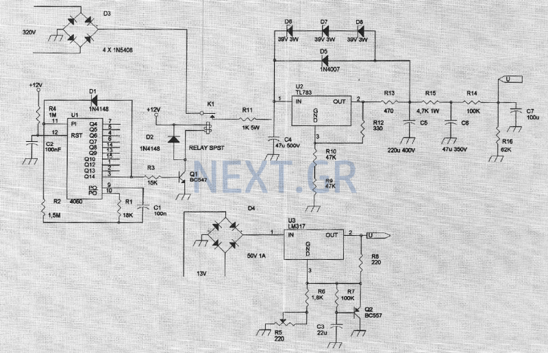
The amplifier feeding the final amplification stage operates with unstabilized voltage. The output stage, utilizing push-pull operation, exhibits significant rejection of the supply voltage. However, the earlier stages do not provide the same level of rejection, resulting in unwanted...

Although LEDs dominate the lighting market today, a standard flashlight bulb can still be a viable light-emitting option, particularly due to its simpler configuration compared to an LED. When the AC mains supply fails, transistor T1 becomes forward-biased, allowing...
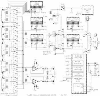
This circuit is not easy to build, but it provides excellent audio quality. It serves as a high-quality preamplifier, capable of driving high-quality power amplifiers while delivering good sound. The described circuit functions as a high-fidelity audio preamplifier, designed to...
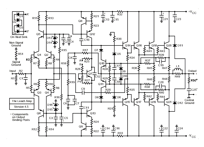
A hot topic of amplifier design in the 1970s was "transient intermodulation distortion" (TIM). Other names which were used for this phenomenon were "slewing induced distortion" (SID), and "dynamic intermodulation distortion" (DIM). TIM occurs when a transient input signal...
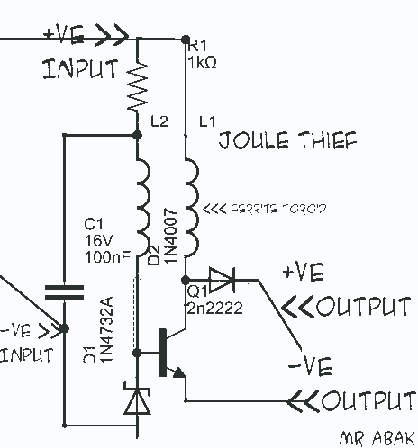
This circuit diagram is provided for those interested. It is a small circuit that takes an input of 1.5 volts and outputs 120 volts. The circuit in question is a voltage step-up converter, commonly referred to as a boost converter....
The roles of capacitors C1, C4, and C5 in a circuit may not be immediately clear. Capacitors on the power rail help to smooth out the signal by reducing current ripple, which can be observed using an oscilloscope. Resistors...