
cheap emergency light circuit diagram

In this circuit, the flashlight bulb serves as the primary light source, while the battery acts as a backup power supply. The operation of the circuit is dependent on the behavior of transistor T1, which is typically configured as a switch. During normal operation, when AC mains power is available, the transistor remains off, preventing current from flowing from the battery to the bulb.
Upon detection of a power failure, the voltage at the base of T1 rises due to the absence of the AC signal, leading to its forward biasing. This allows current to flow from the battery through T1, illuminating the flashlight bulb. The circuit may also include a diode in parallel with the bulb to prevent reverse current flow, thus protecting the transistor and ensuring reliable operation.
In addition, a resistor may be placed in series with the base of T1 to limit the base current and prevent damage to the transistor. The choice of the flashlight bulb rating should correspond to the battery voltage to ensure optimal performance and brightness.
Overall, this simple yet effective circuit design provides an emergency lighting solution that leverages the reliability of traditional flashlight bulbs while offering a straightforward implementation that can be easily configured and maintained.Though it`s the world LEDs today, an ordinary flashlight bulb can also be considered a useful light emitting candidate especially because it`s much to configure than an LED. However, the moment AC mains fails, T1 is instantly forward biased, it conducts and allows the battery power to pass through it, which ultimately turns ON the bulb and the emergency light.
🔗 External reference
Related Circuits

A simple three-band graphic equalizer circuit is constructed using a single op-amp IC, the LF351 (IC1), along with several passive components. The component values in this circuit are not highly critical, allowing for substitutions with nearby values that result...
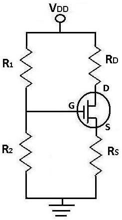
During DC analysis, all AC voltage sources are removed from the circuit since they are AC sources. DC analysis focuses solely on DC sources. Additionally, all capacitors are removed because, in a DC context, capacitors act as open circuits....
Crystal Y1 generates a fundamental frequency clock signal of 14.31818 MHz. U31 is a Dual Voltage Controlled Oscillator (VCO) that produces a 14.31818 MHz clock signal, referred to as the color clock, at pin 10. The output frequency can...

The use of logic symbols results in a diagram that allows users to determine the operation of a component or system as various input signals change. To read and interpret logic diagrams, one must understand the meaning of each...

The circuit utilizes a 555 timer as the core component to create an astable multivibrator. The oscillation period T is given by the formula T = 0.693 (R1 + 2R2) C1, which corresponds to an oscillation frequency of approximately...

The circuit depicted in Figure 3-98 demonstrates how motor starting and low-speed operation are managed using switch SA. By adjusting the time relay KT, the motor's operation can transition from low speed to high-speed operation within a specified time...