
150W Power Amplifier

The 150W power amplifier circuit is designed to deliver high output power, suitable for various audio amplification applications. The circuit employs three types of power transistors: TIP41, TIP142, and TIP147, which are known for their robust performance in high-current and high-voltage scenarios.
In this configuration, the TIP41 transistor serves as the driver stage, responsible for amplifying the input signal to a level sufficient to drive the output stage. The TIP142 and TIP147 transistors are configured in a complementary push-pull arrangement, allowing for efficient amplification of both halves of the audio signal. This arrangement minimizes distortion and improves overall sound quality.
The circuit can be powered by a dual power supply, typically providing a voltage range of ±30V to ±40V, which is conducive for achieving the desired output power. Proper heat sinking is critical for the TIP transistors to prevent thermal runaway and ensure reliable operation under continuous load conditions.
Input capacitors may be used to block any DC offset from the input signal, while feedback resistors can be incorporated to stabilize the gain and improve linearity. Bypass capacitors should be placed close to the power supply pins of the transistors to filter out high-frequency noise, enhancing the amplifier's performance.
This amplifier design does not require a PCB, making it accessible for hobbyists and engineers who prefer to build circuits on a breadboard or custom layout. However, careful attention to component placement and wiring is necessary to minimize parasitic inductance and capacitance, which can adversely affect performance.
Overall, this 150W power amplifier circuit provides a powerful solution for audio applications, combining simplicity in construction with effective performance.150W power amplifier circuit diagram based power transistor TIP41/TIP142/TIP147.It is easy enough to built without PCB. The power output range is about 100-150W. 🔗 External reference
Related Circuits
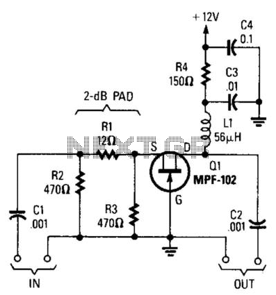
Using an MPF102 JFET, this circuit has a 50-ohm input impedance. The load impedance should be approximately 470 ohms. A 3:1 matching transformer can be utilized to return the impedance to 50 ohms. This circuit will exhibit a gain...
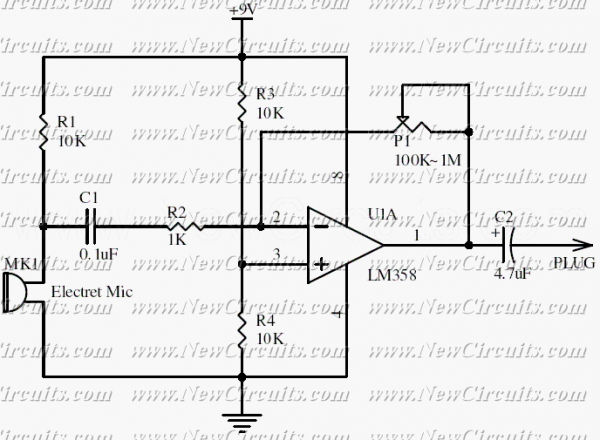
This circuit will be useful if you have an electret microphone that produces a low audio (sound) level and you want to connect it to an amplifier or something like it. The circuit boosts the microphone output voltage to...
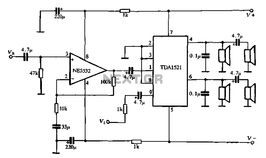
Active speaker with amplifier circuit TDA1521 and NE5532, featuring dual-channel input and dual-channel output. The active speaker circuit utilizes the TDA1521 integrated circuit, which serves as the power amplifier. This IC is designed for high-efficiency amplification, providing a robust output suitable...

A compact audio amplifier circuit utilizing the TDA 7052 integrated circuit from Philips. This circuit is suitable for use as a pocket radio amplifier, delivering an output power of 2 watts. The TDA 7052 is a low-voltage audio amplifier designed...
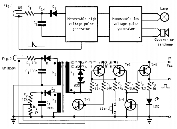
In the absence of radiation, no current is drawn. At normal background radiation levels, the power consumption is extremely low. The instrument may be left on for several months without changing batteries. In this way, the detector is always...
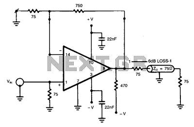
The NE5539 wideband operational amplifier can be easily configured as a color video amplifier. The gain remains stable, varying by less than 0.5% from the lowest to the highest state. The maximum differential phase shift is approximately +0.1. The...