
Active speaker amplifier circuit

The active speaker circuit utilizes the TDA1521 integrated circuit, which serves as the power amplifier. This IC is designed for high-efficiency amplification, providing a robust output suitable for driving speaker loads. The TDA1521 operates with a supply voltage ranging from 12V to 28V, allowing for flexibility in power supply design. It incorporates thermal protection and short-circuit protection, ensuring reliable operation under varying load conditions.
The NE5532 is employed in this circuit as a low-noise audio operational amplifier, providing high fidelity signal processing. This dual-channel op-amp is known for its excellent bandwidth and slew rate, making it ideal for audio applications. It can be configured in various ways, such as inverting or non-inverting configurations, to suit the specific requirements of the audio signal path.
In this design, the dual-channel input allows for stereo audio signals to be processed, with the NE5532 amplifying the incoming audio signals before they are fed into the TDA1521 for final amplification. The output stage of the TDA1521 drives the connected speakers, delivering clear and powerful sound reproduction.
The circuit typically includes additional passive components such as resistors and capacitors for biasing, filtering, and stability purposes. Proper layout and grounding techniques are crucial to minimize noise and interference, ensuring optimal performance of the active speaker system. Overall, this configuration is well-suited for applications requiring high-quality audio amplification in compact designs.Active speaker with amplifier circuit TDA1521 and NE5532 composed of dual-channel input dual channel output.
Related Circuits

The following circuit illustrates a simple 100W inverter circuit diagram. This circuit is based on the CD4047 integrated circuit (IC). Features include low power CMOS technology. The simple 100W inverter circuit utilizes the CD4047 IC, which is a versatile device...
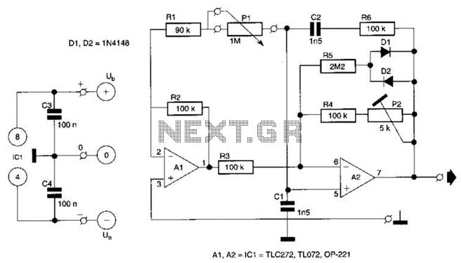
This circuit utilizes a single potentiometer to control a frequency range from 300 Hz to 3000 Hz. A FET operational amplifier is employed at stages A1 and A2. The upper frequency limit is dictated by the gain-bandwidth product of...
This circuit diagram is provided for those interested. It is a small circuit that takes an input of 1.5 volts and outputs 120 volts. The circuit in question is a voltage step-up converter, commonly referred to as a boost converter....
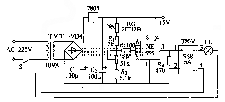
The NE555 time base circuit with an AC solid-state relay (SSR) can function as an automatic light switch circuit. The circuit diagram illustrates that during the day, the incandescent light is turned off due to the influence of the...
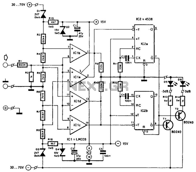
This circuit was utilized with an audio power amplifier to identify the point at which the output is -3 dB from maximum, indicated by LED D5, and at clipping, shown by LED D6. The indicator can be employed with...
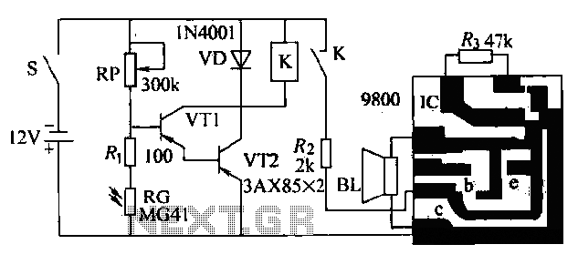
The circuit presented is a second-generation flame alarm for natural gas stoves. After the gas stove is ignited and normal combustion occurs, the power switch S is closed. The photoresistor RG, influenced by the light from the flame, has...