
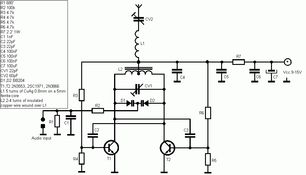
15V Simple FM Transmitter

This FM transmitter circuit is designed for simplicity and efficiency, making it suitable for educational purposes or hobbyist projects. The power supply of 1.5V is sufficient to drive the circuit and allows for portability. The LC resonant circuit, composed of the inductor L1 and the capacitor, is crucial in determining the operating frequency of the transmitter. The specified frequency range of 80 to 110 MHz is typical for FM broadcasting, allowing compatibility with standard FM receivers.
The inductor L1, constructed with 8 turns of No. 22 wire, serves as the primary element in the resonant circuit. The choice of wire gauge and the number of turns directly affect the inductance value, which must be calculated to ensure proper tuning of the circuit to the desired frequency. The physical dimensions of the inductor, with a diameter of 4 to 5 cm, are practical for maintaining a compact design while providing adequate inductance.
The antenna, a 6-inch cable, is connected to the copper half of the inductor, playing a vital role in radiating the modulated signal. The length of the antenna is a critical factor, as it influences the transmission range and efficiency of the signal. The use of a simple cable as an antenna makes the circuit easy to assemble and test.
Regarding component selection, the circuit allows for flexibility in the choice of resistors and capacitors, enabling users to replace components with those of similar values without significantly affecting performance. The 1/4 watt ceramic resistor is suitable for this low-power application, while the 10µF electrolytic capacitor ensures stable operation of the circuit. The inclusion of a variable capacitor (5-60pF) provides the ability to fine-tune the frequency, allowing for adjustments based on the specific requirements of the transmission environment.
Overall, this FM transmitter circuit represents a straightforward approach to frequency modulation, emphasizing ease of construction and adaptability in component selection. Such a design is beneficial for those interested in exploring radio frequency transmission and modulation principles.This simple FM (frequency modulation) transmitter is powered only by a 1. 5V battery and uses only one frequency of this transmitter transistor. The is controlled by the LC resonant circuit and operates from 80 to 110 MHz The inductor L1 is 8 turns of wire wound magnetic No. 22 with diameter of 4 to 5 cm or the diameter of a pencil. The antenna is a 6-inch cable connected to the copper half of the L1 inductor. Other parts are not critical and can be replaced by their nearest value. Resistance 1 / 4 watt ceramic capacitor type and, except for electrolytic capacitor 10uF. 5-60pF capacitor is a type of court or variable rate. 🔗 External reference
Related Circuits
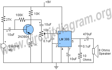
Schematic and description of a simple microphone amplifier circuit. This circuit contains two stages: the first is a microphone preamplifier, and the second is an audio amplifier using the LM386 Amplifier IC. The simple microphone amplifier circuit is designed to...
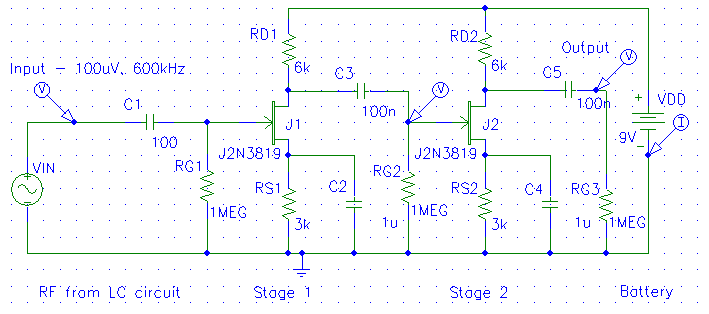
The diagrams below illustrate the development of a simple modular radio receiver based entirely on circuits and devices studied during the Part IA course on Linear Circuits and Devices. This receiver may not revolutionize the market; however, it aims...
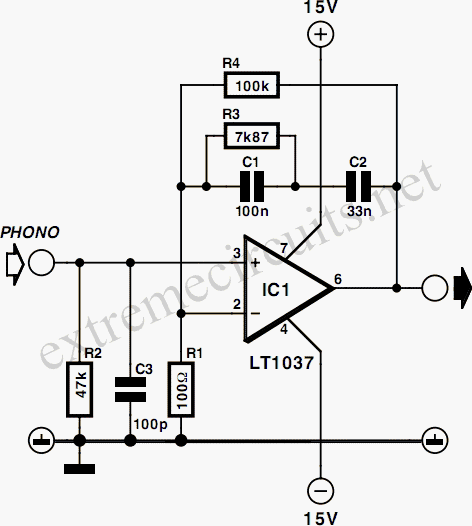
Phonographs are becoming increasingly rare as they are being replaced by more advanced audio systems such as CD players, recorders, and portable MiniDisc player/recorders. This shift is acknowledged by audio equipment manufacturers, leading to the omission of traditional phono...
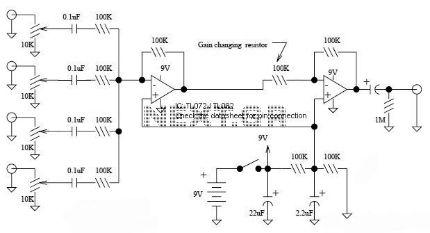
This is a simple mixer featuring four inputs and two operational amplifiers (op-amps). It is designed for mixing microphone signals or effects outputs. The overall gain from input to output is unity when the potentiometer associated with the input...
FM Broadcast Audio Transmitter. The circuit includes a frequency-modulated oscillator, an audio preamplifier with pre-emphasis to provide the frequency-modulating signal, and a buffer amplifier to drive the antenna connector. The FM radio pirate introduction to community radio electronics presents...
Logic-1 and logic-0 represent the states of digital signals, where logic-1 corresponds to a high voltage close to Vcc, and logic-0 corresponds to a voltage near neutral or ground. Logic-0 cannot be transformed into logic-1, while logic-1 can revert...