
Simple Mixer

The circuit consists of two op-amps configured as summing amplifiers, each allowing for the combination of multiple audio signals. The four inputs can be connected to various audio sources, such as microphones or line-level effects, with each input channel equipped with a potentiometer to control the individual signal levels before mixing.
The first op-amp serves as a summing node, where the signals from the inputs are combined. Resistors are used to set the gain and ensure that the output does not exceed the input levels, maintaining audio fidelity. The second op-amp can be utilized for buffering the mixed output, providing a low-impedance output suitable for driving further stages in an audio system, such as amplifiers or speakers.
Power supply considerations for the op-amps are essential, typically requiring a dual polarity supply to accommodate the audio signal swing. Decoupling capacitors should be placed near the power pins of the op-amps to minimize noise and improve stability.
Overall, this simple mixer design is effective for basic audio applications, allowing for flexible mixing of multiple signals with straightforward gain control.Here the simple mixer with 4 input and 2 op-amps: A basic mixer suitable for mixing microphones or even effects outputs. The overall gain from input to output is one if the pot related towards the input is full up. You can make this a net g.. 🔗 External reference
Related Circuits
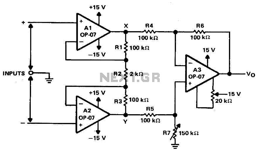
Operational amplifiers A1 and A2 are connected in a non-inverting configuration to form amplifier A3. The operational amplifier A3 can be classified as a subtractor circuit that converts the differential signal between the floating points X and Y into...
The simplest Analog to Digital Converter (ADC) can be constructed as shown in Figure 1. The input voltage, which can range from zero up to the power supply voltage (Vcc), is converted to a parallel binary code at the...
This circuit is a small +5V power supply, which is useful when experimenting with digital electronics. Small inexpensive wall transformers with variable output voltage are available from any electronics shop and supermarket. Those transformers are easily available, but usually...
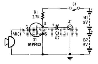
This preamplifier utilizes a small dynamic microphone connected to the gate of Q1. R1 acts as a load resistor. The audio output is taken from the negative side of C1 to ground. The output voltage will range between 10...
A voltage-to-frequency converter can be constructed using the LM231/331 chip, making it a cost-effective solution for applications such as analog-to-digital conversion and frequency-to-voltage conversion over extended periods. The LM231/331 series of voltage comparators can be effectively utilized to design a...
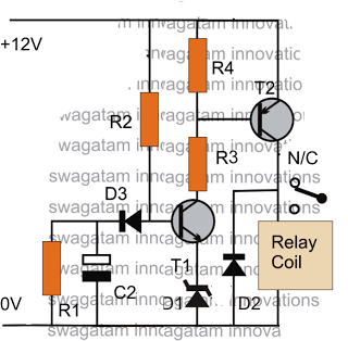
The post discusses a simple delay ON circuit that enables a connected load at the output to be activated with a predetermined delay after the power switch is turned ON. This circuit can be utilized in various applications that...