
15V TOP224Y 2A DC output switching power supply circuit

This circuit design features a 15V DC switching power supply utilizing the TOP224Y regulator, which is well-regarded for its efficiency and compact design. The integration of the NEC2501 optocoupler and the TL431 voltage reference enhances the circuit's ability to maintain stable output under varying conditions. The use of the TL431 as an external error amplifier allows for improved performance by providing feedback that isolates the control loop from fluctuations in the power supply input.
The resistors R4 and R5 are critical for voltage feedback, sampling the output voltage to ensure it remains within the desired range. By setting the appropriate values for R4 and R5, the designer can achieve the necessary voltage division to match the TL431's reference voltage, thus maintaining regulation. The inclusion of capacitor C8 alongside R4 serves to filter any noise and stabilize the feedback loop, ensuring a smooth response to load changes.
The LED current is controlled through the adjustment of the K-side potential, which directly influences the current flowing through the LED and, consequently, the feedback to the TOP224Y. This feedback mechanism allows for real-time adjustments to the output voltage, enhancing the overall stability of the power supply.
The performance metrics indicate that the power supply exhibits minimal variation in output voltage despite significant changes in input voltage and load current, making it suitable for applications requiring high reliability. The additional mention of a 5V isolated switching power supply using the TOP414G further illustrates the versatility of this design approach, allowing for multiple output configurations from a single power supply architecture.Constituted by a 15V TOP224Y, 2A output DC switching power supply circuit shown in FIG. Using three integrated circuits: ICl is a monolithic regulator TOP224Y, IC2 is optocoupl ers NEC2501, IC3 is a precision voltage reference TL431. TL431 (IC3) and the optocoupler NEC2501 (IC2) constituting the electrically isolated external error amplifier, and then with TOP224Y internal error amplifier with the use of TOP224Y (IC1) a control terminal of the current fine adjustment, thus greatly improving the performance of the regulator.+ 15V regulated output by R4, R5 partial pressure sampling voltage obtained with the TL431 internal 2.5V reference voltage, by changing the K-side potential to control the LED current, thereby regulating the control terminal current Ic. Rl is LED current limiting resistor, and can set the control loop DC gain. R4 and C8 also determines the frequency characteristics of the external error amplifier. Regulation accuracy of the power supply with integrated linear power supply comparable: u When the AC input voltage from 85V to change when 265V, Sv 0.2%; When the load current from 10% (0.2A) is changed to 100% (2A time), Sl can reach 0.2%.3.1.8 constituted by a 5V TOP414G, 2A output isolated switching power supply
Related Circuits
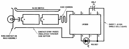
The schematic presented below illustrates the Flashlight Finder circuit diagram utilizing the LM3909, a monolithic oscillator specifically designed for flashing Light Emitting Diodes (LEDs). The Flashlight Finder circuit employs the LM3909 integrated circuit, which is capable of generating a series...
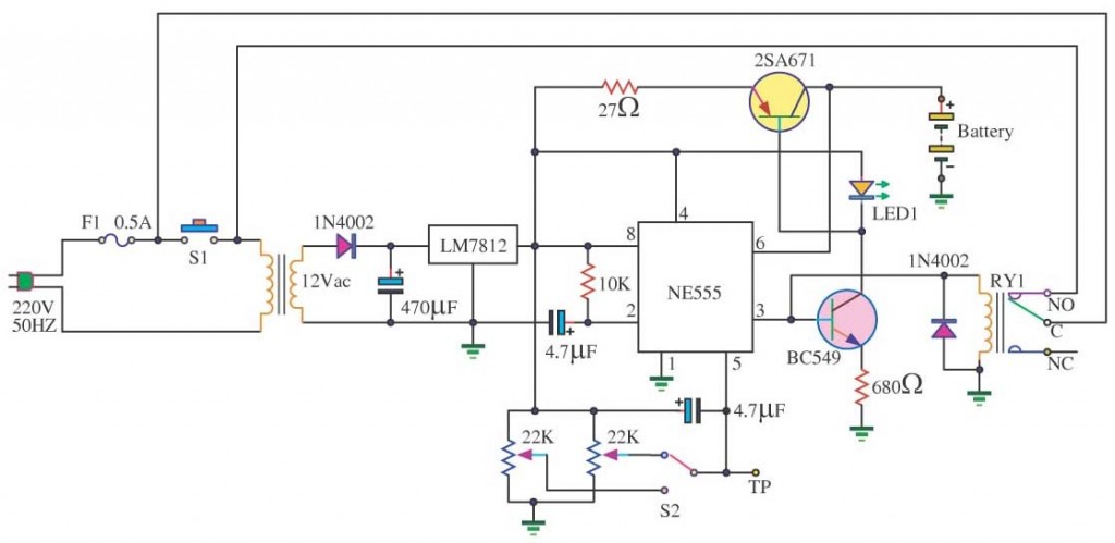
In a lithium-ion cell, a voltage of 3.8V per cell indicates a state of charge of approximately 50%. It is important to note that using voltage as a fuel gauge is not precise, as cells manufactured by different companies...
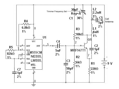
This device functions as a reversal of a radio station, sending a null signal to a selected frequency to eliminate the actual broadcast. The radio transmitter operates at a loss of 10,000W; therefore, this circuit is intended for use...
This circuit switches a printer's USB connection from a PC to a laptop. The objective was to create a solution that enables a laptop to use the printer intermittently while maintaining the printer's primary connection to the PC. Instead...

I will also explain how you can build a 1.5W PA transmitter. The project will include PCB, components and instructions how to make coils, assembly and testing. First let's discuss and learn about the RMS value of a sine...
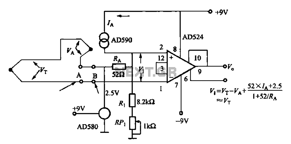
The AD524J type thermocouple cold junction temperature compensation circuit is illustrated in Figure 1-20. This circuit utilizes J-type thermocouples, with the base reference voltage sourced from the AD580, an integrated temperature sensor, and the precision instrumentation amplifier AD524. The...