
radio station blocker circuit

The circuit described operates on the principle of signal jamming, specifically targeting a designated frequency to disrupt existing broadcasts. The device generates a blank or null signal that effectively overrides the transmission from the intended radio station. This approach is particularly useful in scenarios where interference with a specific broadcast is required, such as in testing environments or for experimental purposes.
The transmitter circuit is designed to operate at a power output of 10,000W, which is substantial and indicates that the device is capable of producing a strong enough signal to interfere with nearby radio communications. The close-range operation is crucial, as the effectiveness of the jamming signal diminishes with distance from the target frequency source. The design must account for the characteristics of the radio waves, including their propagation and attenuation in the surrounding environment.
To ensure optimal performance, the device should be positioned in proximity to the receiving antenna of the targeted radio station. This positioning allows the null signal to dominate the frequency, effectively canceling out the original broadcast. The circuit schematic would typically include components such as oscillators, amplifiers, and filters to generate and modulate the jamming signal accurately.
The inclusion of RF components must be carefully calculated to match the frequency characteristics of the target broadcast. Additionally, considerations for heat dissipation and power management are essential, given the high power output of the transmitter. Proper shielding and grounding techniques should also be employed to minimize unintended interference and ensure compliance with regulatory standards regarding radio frequency emissions.
Overall, the design of this device requires a thorough understanding of radio frequency principles, circuit design, and regulatory compliance to function effectively and safely in its intended application.This device is reversal of a radio station, because it sends an empty signal to the frequency chosen in order to remove the actual broadcast. Removing broadcasting Is the radio transmitter would be lost 10. 000W, yes we only use this circuit at close range only, because the utility block radio station not far away.
This device needs to close t o the antenna radio receiver, at least according to the ammount of radio frequency ( RF ). To the circuit schematic can be see below. 🔗 External reference
Related Circuits
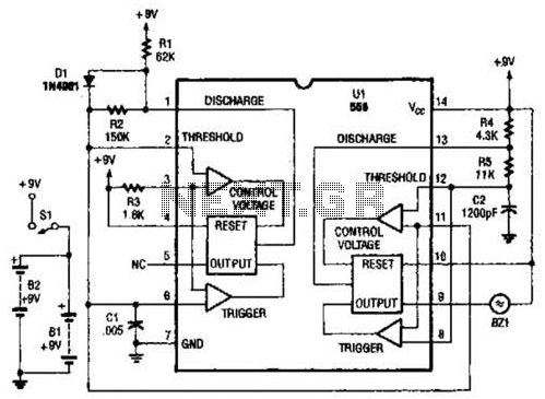
The two timers in the bug repeller exhibit notable characteristics. Both have their thresholds set externally; the oscillator on the left operates with a 50% duty cycle, while the oscillator on the right functions as a voltage-controlled oscillator (VCO). The...
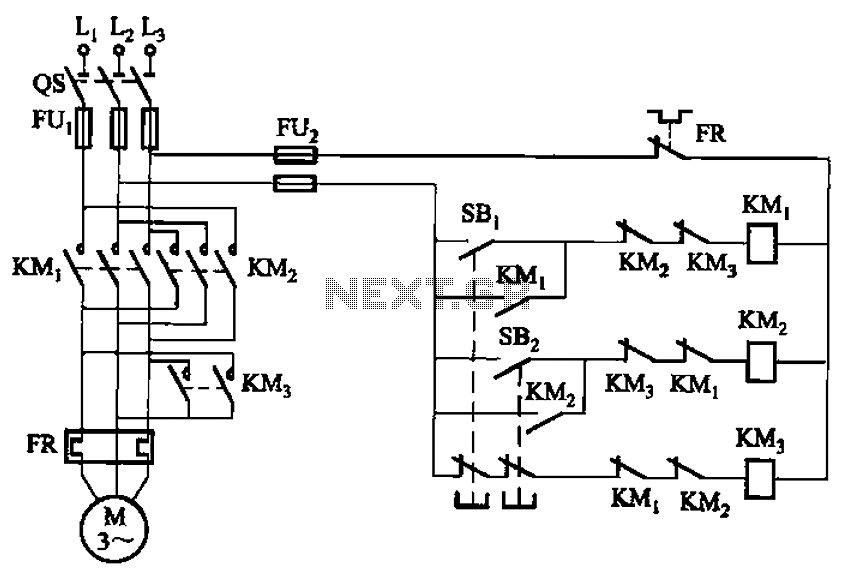
The circuit depicted in Figure 3-154 illustrates the KM3 braking contactors. During shutdown, the system can disconnect the operating system. At this point, KM3 activates, causing its normally open contact to close, thereby shorting the three-phase stator windings to...
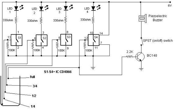
A simple and cost-effective water level indicator circuit can be designed using this schematic. This water level indicator utilizes a CMOS IC CD4066 to indicate the amount of water present in an overhead tank and to provide an alarm...
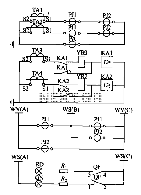
Expanding schematic circuit for the secondary circuit of high-voltage lines. The schematic circuit for the secondary circuit of high-voltage lines is designed to enhance the distribution and management of electrical power in high-voltage systems. This circuit typically includes components...
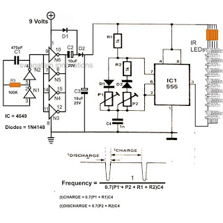
The 4049 section serves as a fundamental voltage doubler circuit, enhancing a 9 V supply to approximately 15 V. This elevated voltage subsequently acts as the supply voltage for the following 555 pulse modulator section. A key characteristic of...
This is an enhanced infrared (IR) remote control extender circuit. It features high noise immunity, resistance to ambient and reflected light, and an extended range of approximately 7 meters from the remote control to the extender circuit. It is...