
15W FM RF Amplifier with 2SC2539

The FM transmitter circuit is designed to operate efficiently within the FM band, utilizing the BF494 transistor for audio modulation. The circuit's architecture allows for a straightforward assembly process, making it accessible for hobbyists and professionals alike. The MFE201 transistor serves as the core component for the common-emitter configuration, which is essential for achieving the desired amplification and signal clarity.
In addition to the FM transmitter, the shortwave transmitter based on the BEL1895 IC expands the project’s versatility, enabling communication over a broader frequency range. The incorporation of a microphone amplifier allows for direct audio input, which is crucial for applications in educational settings or experimental setups. The variable frequency oscillator provides flexibility in tuning, ensuring that the transmitter can adapt to different operational environments.
The RF amplifier circuit is a critical component in enhancing signal strength, making it ideal for applications that require robust signal transmission. The design utilizes the 2SC1970 transistor, known for its reliability in RF applications, ensuring that the circuit can handle the necessary power levels while maintaining performance. This circuit can be further optimized by experimenting with different transistor types, allowing for customization based on specific requirements or constraints.
Overall, this collection of circuits offers a comprehensive solution for various RF and audio transmission needs, demonstrating the potential for both educational and practical applications in electronics.This the Good Quality FM transmitter for your stereo or any other amplifier gives you a pretty good signal strength up to a range of 500 metres having a power output of about 200 mW. This circuit can be operated with a 9V battery. The audio-frequency modulation stage is constructed close to transistor BF494 (T1), . By working with only a small han dfull of parts you can assembled this kind of reliable FM Amplifier. It runs with only 1 UHF/VHF type transistor, MFE201. This amplifier will pull in all distant FM stations clearly. The circuit is configured as a common-emitter tuned RF pre-amplifier wired around VHF/UHF transistor MFE201. You will find. Here the SW transmitter circuit based on IC BEL1895. This particular transmitter circuit works in shortwave HF band (6 MHz to 15 MHz), and can be applied for shortrange communication and for educational purposes.
The circuit is composed of a mic amplifier circuit, a variable frequency oscillator, and modulation amplifier stages. Transistor T1 (BF195) is. Easy FM tracking transmitter project :). The circuit designed by Tony van Roon, and here the FM tracking transmitter diagram: Components List: R1 = 10K C1 = 100uF/10V C2 = 10nF C3 = 4-40pF trimmer capacitor C4 = 4.
7pF IC1 = LM3909 Q1 = 2N3904 NPN transistor LED1 = Red LED/or another color as you. This diagram is a schematic diagram of RF amplifier circuit. The circuit will amplify the RF signal about 10 times, 100mW input power to 1. 3W output power. It use a general NPN RF transistor 2SC1970. You may apply other transistors, for example 2N442. Circuit Diagram: Circuit Works: RF system and specially in RF amplifiers, this. 🔗 External reference
Related Circuits
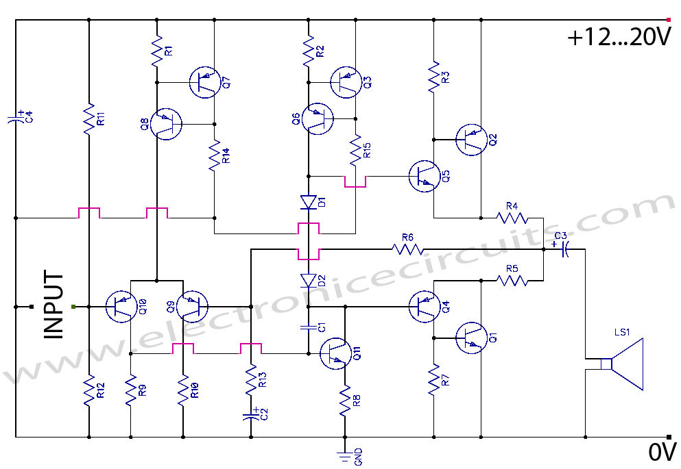
Discrete Class AB Transistor Audio Power Amplifier Circuit Diagram. This is a Class AB transistor power amplifier. It is a simple amplifier. The discrete Class AB transistor audio power amplifier is designed to provide efficient amplification of audio signals while...
A unit which is often very useful, if we need to isolate, in sound circuits, two stage between them. Then we can use this circuit which has an amplified unit, which gain X1, we do not use total negative...
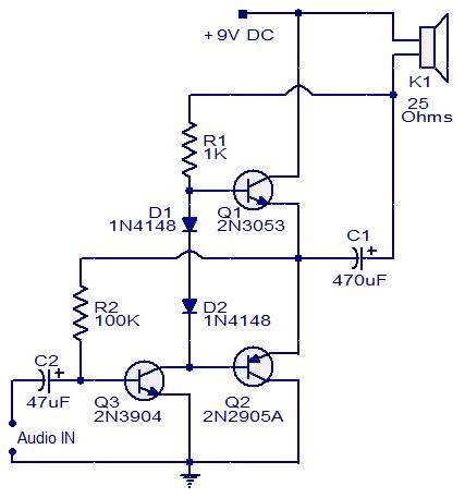
This circuit diagram illustrates a simple three-transistor audio amplifier capable of delivering approximately 100 mW of power to a 25 Ohm speaker. Diodes D1 and D2 provide a constant bias voltage for transistors Q1 and Q2. Transistor Q1 functions...
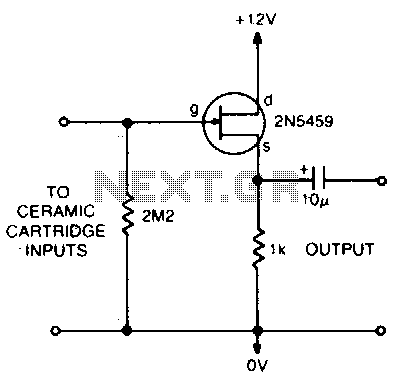
This circuit matches the very high impedance of ceramic cartridges, providing unity gain and low impedance output. By "loading" the cartridge with a 2.2MΩ input resistance, the cartridge characteristics are adjusted to closely compensate for the RIAA recording curve....
For some time, a variety of tape cassette decks have been available at low prices from mail order businesses and electronics retailers. These decks do not contain any electronics. Building a recording amplifier and the fairly complex magnetic biasing...
This classic tube amplifier was once considered the best value available. Fifteen years ago, it could be purchased for $25. The amplifier was designed to be affordable while maximizing performance for the cost. At the end of its production,...