
16-bit adjustable reference uses 8-bit digital potentiometers

The described circuit is a sophisticated programmable precision voltage reference that utilizes a 16-bit digital-to-analog converter (DAC) architecture. This design incorporates three 8-bit digital potentiometers, which are configured to function as multiplying DACs. The precision reference output is characterized by a least significant bit (LSB) value of 62.5 µV, indicating a high level of resolution suitable for applications requiring fine voltage adjustments.
In the schematic, the digital potentiometers (IC3A and IC3B) are connected in a way that spans the reference voltage (VREF) to ground. This configuration allows for the precise adjustment of the output voltage through the wiper terminals of the potentiometers. The wiper outputs of both IC3A and IC3B are routed to the noninverting inputs of two operational amplifiers (IC4A and IC4B). These amplifiers serve to buffer and amplify the signals from the digital potentiometers, ensuring that the output voltage remains stable and accurate despite variations in load conditions.
The use of CMOS op-amps in this design is advantageous due to their low power consumption and high input impedance, which minimizes the loading effect on the digital potentiometers. The combination of the digital potentiometers and operational amplifiers allows for precise control over the output voltage while maintaining a compact and efficient circuit design.
This configuration can be particularly useful in applications such as precision instrumentation, calibration systems, or any scenario where a highly accurate and programmable voltage reference is required. By adjusting the digital inputs to the potentiometers, the output voltage can be finely tuned, enabling a wide range of voltage settings suitable for various electronic applications.It may be easy to find a precision voltage reference for your application; however, a programmable precision reference is another matter. The circuit in Figure 1 yields a precision reference with an LSB of 62.5 µV. The circuit is a 16-bit DAC using three 8-bit digital potentiometers and three CMOS op amps. Each digital potentiometer operates as an 8-bit multiplying DAC. On the left side of Figure 1, two digital potentiometers, IC3A and IC3B, span across VREF to ground, and the wiper outputs are connected to the noninverting inputs of two amplifiers, IC4A and IC4B.
🔗 External reference
Related Circuits
This circuit charges two NiCad cells with a constant current and features dual charging rates, voltage cutoff, and an audible alarm. The circuit is powered. This circuit is designed to efficiently charge two nickel-cadmium (NiCad) cells, utilizing a constant current...
The circuit begins timing upon activation. A green LED illuminates to indicate that timing is in progress. Once the designated time period elapses, the green LED turns off, the red LED activates, and a bleeper emits sound. The duration...
The current source IC Type LM334 is utilized in this specialized application, which features a minimal temperature coefficient and operates with a very low current draw of only 10 µA at room temperature. This current increases slightly with higher...
The ATmega8 microcontroller-based Low-Cost Telemetry Device (LTD) is an efficient telemetry keyer. The LTD measures the voltage levels of up to four analog channels via its on-chip 10-bit ADC, converts the measurements to numbers, and then sends the data...
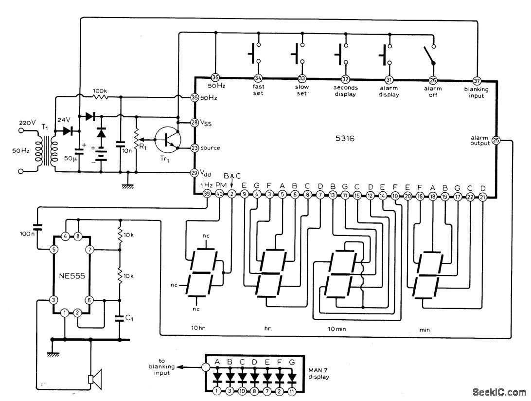
The circuit utilizes the MM5316 alarm-clock integrated circuit (IC), which is originally intended for driving LCD or fluorescent displays. In this implementation, it has been adapted for use with LED display diodes. The system is designed to operate on...
The challenge is to control the speed of the motor. One approach is to use a plane, radio, and speed control integrated with the motor, but this is not ideal. Alternatively, mounting the motor on a bench and directly...