
Low-Power Voltage Reference

This circuit utilizes the LM334 current source IC, which is known for its low temperature coefficient and minimal current draw, making it suitable for precision applications. The design incorporates a bandgap reference technique, which leverages the characteristics of the LM334 and a transistor to maintain a stable output voltage across varying temperatures. The combination of the positive temperature coefficient of the LM334 and the negative temperature coefficient of the transistor's base-emitter junction effectively cancels out temperature-induced variations in output voltage.
The output voltage is meticulously set to 1.253 V, which is a common reference voltage for precision applications. The adjustment of potentiometer P1 allows for fine-tuning of this voltage, but it is crucial to replace the adjustable components with fixed resistors after calibration to ensure long-term stability and accuracy. The use of a 1% tolerance metal-oxide film resistor from the E96 series enhances the precision of the circuit.
The reference circuit's design includes a negative output resistance feature, achieved through the configuration of IC1, which stabilizes the output against variations in load current. Resistor R3 plays a vital role in maintaining the desired output resistance, ensuring that the circuit can supply a stable load current without significant fluctuations.
The performance metrics of this reference circuit are noteworthy, with minimal output voltage variation despite significant changes in input voltage. This characteristic makes it suitable for applications requiring high precision, such as in instrumentation and measurement systems. The temperature coefficient, which can be reduced to as low as 5 ppm/°C with careful calibration, indicates the circuit's reliability in maintaining output stability across temperature variations.
Overall, this circuit exemplifies a sophisticated approach to voltage reference design, combining low power consumption, high precision, and excellent thermal stability, making it a valuable component in various electronic applications.The present reference is a special application of current source IC Type LM334. It has a tiny temperature coefficient and draws only a minute current: at room temperature, only 10 µA, which increases with large rises in temperature by only a few µA. The circuit is basically a bandgap reference, because the positive temperature coefficient of the LM334 is combined with the negative temperature coefficient of the base-emitter junction of a transistor (which ensures good thermal coupling). To obtain a temperature coefficient of zero, or very nearly so, the output voltage of the circuit is adjusted to exactly 1.
253 V with P1. It is, therefore, advisable to measure the set value of P1 accurately after it has been adjusted and to replace the combination of R1+P1 by a fixed resistor of the precise value. Use a 1% metal-oxide film type from the E96 series. Since current source IC1 is tapped at the control input, a reference source with a negative output resistance of about 3.
8 k ensues. Resistor R3 ensures that the ultimate output resistance is about 400 . The load current is then limited to not more than 5 µA. The performance of the reference is good: when the input voltage is increased from 5 V to 30 V, the output voltage varies by only 0. 6 µV (from 1, 2530 V to 1. 2536 V). The temperature coefficient stays below 50 ppm °C 1, and, with careful adjustment, may even come down to 5 ppm °C 1.
The current drawn by the prototype is 9. 8 µA at an ambient temperature of 22 °C. 🔗 External reference
Related Circuits
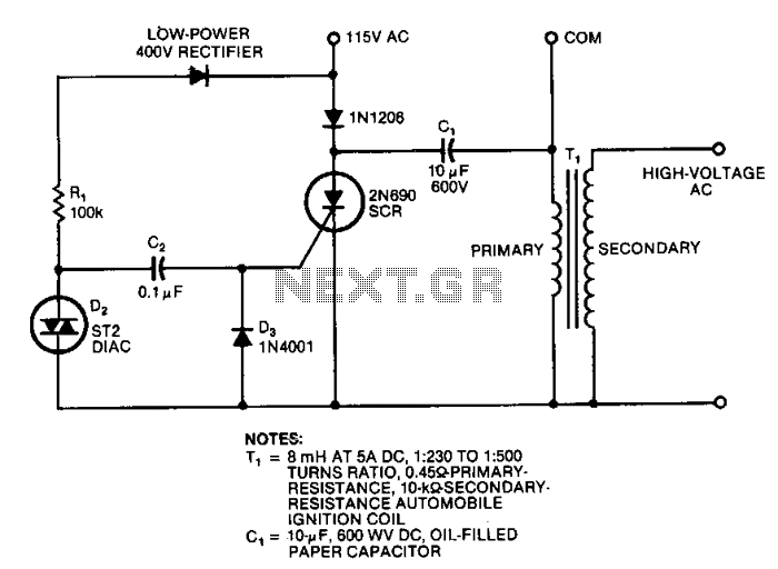
This circuit generates high-voltage pulses using an inexpensive auto ignition coil. By adding a rectifier to the output, the circuit produces high-voltage direct current (DC). The input to the circuit is 115 Vac. During the positive half cycle of...
Converting current into voltage is undesirable for two reasons: first, an impedance is inserted into the measuring line, causing an error; second, amplifier offset voltage is also amplified, leading to a subsequent loss of accuracy. The use of a...
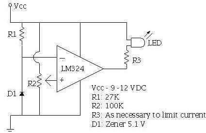
An ECU must have a way to monitor battery voltage. Here is a simple op-amp based circuit which will illuminate the LED when the battery voltage drops to a certain level. The turn-on point is set with R2. You...
The ADF4107 Frequency Synthesizer can be used to implement local oscillators in the upconversion and downconversion sections of wireless receivers and transmitters. It consists of a low noise digital phase frequency detector (PFD), a precision charge pump, a programmable...
This circuit utilizes an LM11 operational amplifier configured as a voltage follower with an input resistance of 1 GΩ, constructed using standard resistor values. When the input is left disconnected, the input offset voltage is amplified by the same...
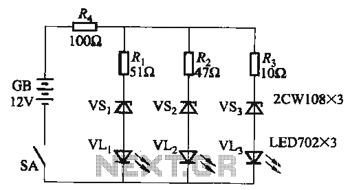
When the supply voltage falls below 10.2V, the yellow light-emitting diode (LED) VLi illuminates, indicating that the storage pool can no longer continue to discharge. Additionally, when the voltage exceeds 16.2V, the yellow, green, and red light-emitting diodes (LEDs)...