
16 bit Analogue to Digital Converter LTC1052

The input voltage range for this A/D converter is specified to be from 0 to 5 volts.
This A/D converter circuit integrates several key components to achieve its functionality. The operational amplifier (A2) serves as a critical element in amplifying the analog signal before conversion. The choice of the LTC 1052 is particularly important due to its low drift characteristics, which help maintain accuracy in the conversion process by minimizing any offset errors that could arise from temperature fluctuations.
The flip-flop within the circuit plays a vital role in storing the converted digital output, ensuring that the data remains stable during the conversion process. Logic gates are incorporated to facilitate the necessary control logic for the conversion sequence, enabling the circuit to function effectively as an A/D converter.
The current sink is essential for providing a stable reference current, which aids in the current balancing technique employed in the circuit. This technique is crucial for achieving high precision in the conversion, as it ensures that the input signal is accurately represented in the digital domain.
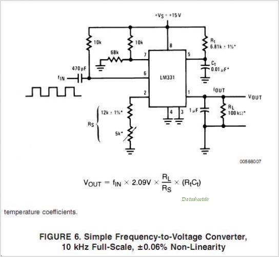
Overall, the design of this A/D converter circuit is tailored to provide reliable and accurate conversion of analog signals within the specified input range, making it suitable for various applications in electronic systems requiring precise digital representation of analog inputs.The circuit here is a A/D converter, that consisting of A2, a flip-flop, some doors and a current sink, is based on a current balancing technique. Again, the stabilized LTC 1052 50 no drift of V input 1 ° C is necessary to eliminate the offset errors of aid.
Input has to be from 0-5V.
Related Circuits
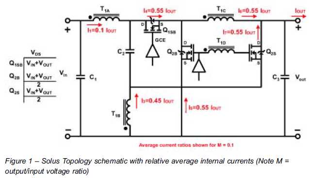
The ability to reduce power losses is crucial. This document describes a new ultra-high-performance topology that is expected to serve as the foundation for next-generation DC-DC power supplies in high-demand applications. The proposed ultra-high-performance topology aims to significantly enhance the...
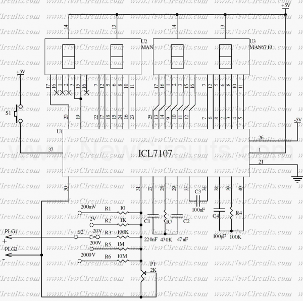
The ICL7107 is a 3 1/2 digit LED A/D converter. It contains an internal voltage reference, high isolation analog switches, sequential control logic, and the display drivers. The auto-zero adjust ensures zero reading for 0 volts input. The ICL7107 is...
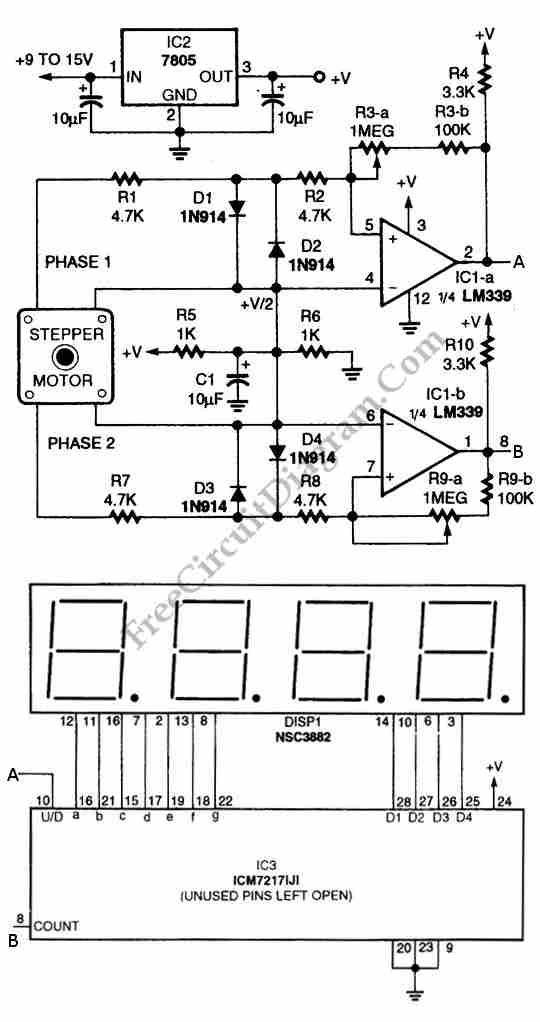
The circuit illustrated in the schematic diagram below allows for the visualization of the direction and shaft rotation of a stepper motor on an LED display. Instead of employing a digital rotation encoder as an input, this circuit utilizes...
This circuit is a digital radar speedometer that measures the speed of moving objects, particularly vehicles such as cars. The speed is displayed in kilometers per hour (KPH) using a three-digit display. The radar operates on the principle of...
This circuit employs a digital voltmeter, consisting of IC1 and IC3, to indicate fuel quantity as a percentage of a full tank. It is designed to accommodate two types of fuel sensors: one with low resistance indicating a full...
The LM2889 is designed to interface audio and video signals to the antenna terminals of a television receiver. It consists of a sound subcarrier oscillator, an FM modulator, a video clamp, and RF oscillators and modulators for two low-VHF...