
Digital Encoder Circuit Using Stepper Motor

The circuit operates by utilizing a stepper motor, which is a type of motor that divides a full rotation into a number of equal steps. This allows for precise control of the motor's position and speed. The LED display serves as a visual output, indicating the current direction of rotation and the specific position of the motor shaft.
The schematic typically includes a microcontroller that processes input signals and determines the appropriate step sequence for the stepper motor. The microcontroller interfaces with the motor driver, which amplifies the control signals to drive the motor coils. The stepper motor is connected to the driver in a configuration that allows for full-step or half-step operation, depending on the desired resolution.
The LED display is connected to the microcontroller, which sends signals to illuminate specific segments of the display based on the motor's position and direction of rotation. This feedback mechanism is crucial for applications where precise motor control and real-time monitoring are necessary.
In summary, this circuit effectively combines a stepper motor with an LED display to provide a comprehensive solution for visualizing motor position and direction, replacing the need for more complex digital encoders while maintaining accuracy and reliability in motor control applications.Using circuit depicted in the schematic diagram below, the direction and shaft rotation of stepper motor can be seen on the LED display. Alternative to digital rotation encoder as a digital encoder input, this circuit uses a stepper motor.
Here is the schematic diagram of the circuit: 🔗 External reference
Related Circuits
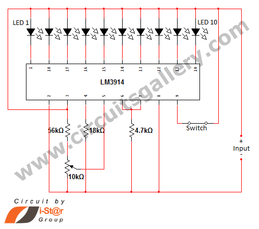
In various situations, it is necessary to indicate the amount of battery charge using methods such as LED dot displays or LED bar displays. This circuit utilizes the LM3914 integrated circuit to serve as a battery charge indicator with...
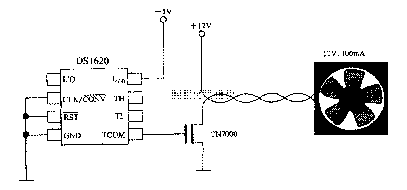
The DS1620, in conjunction with a microprocessor, is utilized to monitor temperature. By controlling the fan, the thermal conditions of the chip can be adjusted to establish a temperature control circuit as illustrated in the accompanying figure. The system...
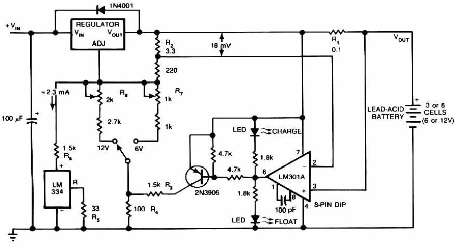
Lead-Acid Battery Charger circuit diagram. The LM301A compares the voltage drop across R1 with an 18 mV reference set by R2. The comparator's output controls the voltage regulator, forcing it to produce the lower float voltage when the battery-charging...
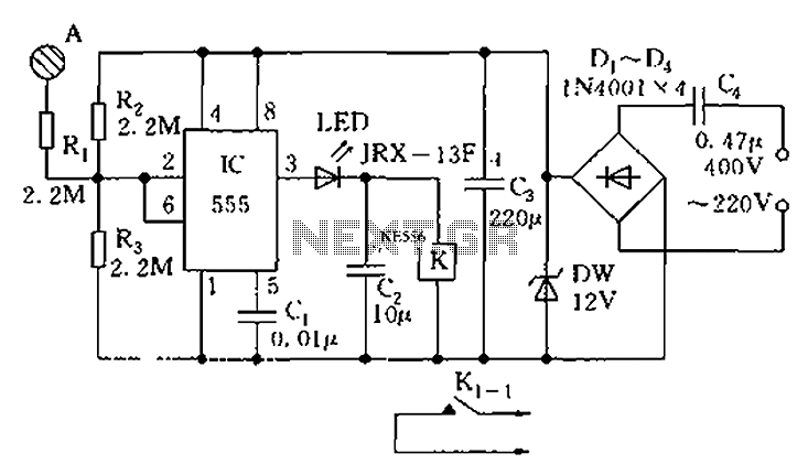
The touch sensor switch circuit diagram features a step-down rectifier circuit, a 555 timer, and flip-flops. When a hand touches the metal sheet A, the sensor signal activates the internal comparator of the 555 timer, setting the output to...
This low-noise microphone amplifier is built with the MAT02 produced by PMI. This microphone amplifier is highly efficient and features a very low noise level. The amplification can be set to either 20 dB or 23.5 dB (10x or...
The circuit diagram for a multiple output digital camera power supply using the MAX1802 is illustrated below. The MAX1802 chip features two buck converters and three boost converters. It accepts an input voltage range of 2.5 to 11V and...