
16 Step Analog Sequencer circuit

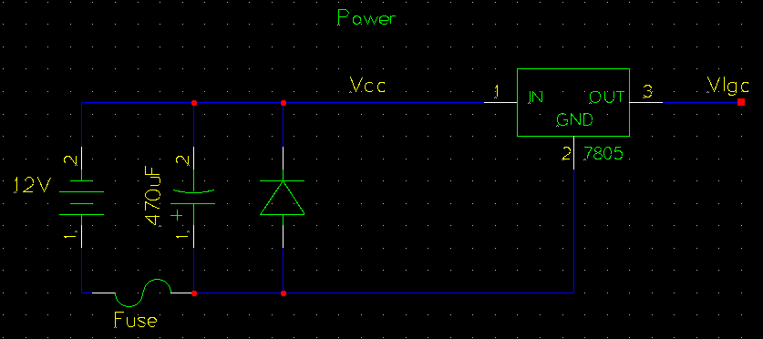
The described analog sequencer circuit utilizes a 4067N multiplexer/demultiplexer, which serves as the core component to manage the signal routing for each step in the sequence. The 16-step sequencer operates by sequentially activating each step based on a clock signal generated by a 555 timer. The 555 timer is configured in astable mode, producing a continuous square wave output that serves as the timing reference for the sequencer. This clock signal determines the rate at which the sequencer advances through its steps.
Each step in the sequencer can be associated with various sound-shaping parameters, which can be manipulated to create unique audio outputs. The SN76477 chip is particularly suited for this purpose, as it is a versatile sound generator capable of producing a range of tones and effects. The integration of the 4063N allows for dynamic control over the number of active steps in the sequence, providing flexibility in performance and composition.
The circuit design incorporates indicator lights to provide visual feedback on the active step, enhancing user interaction. The current iteration primarily focuses on the basic functionality of the sequencer, with further refinements planned to improve the musicality and complexity of the output. The final implementation is expected to include additional features such as variable step lengths, different waveforms, and modulation options, significantly expanding the creative possibilities for sound design.
As the project progresses, thorough testing and evaluation of each component's performance will be essential for ensuring reliability and achieving the desired sound quality. Collaboration and feedback from experienced circuit designers will be invaluable in refining the design and addressing any challenges encountered during the development process.The following video is of my test circuit of a 16 step analog sequencer based on Mauno Tuominen`s schematic for an analog CMOS sequencer based around at 4067n multiplexer/demultiplexer. You can see a DIY version of the sequencer here at studiomanus. com. I had an old sn76477 which I had been planning on turning into something so I started with the basics indicator lights, tempo, and a simple oscillator.
The eventual plan is to expand this out into a large 16 step sequencer/synth based around the sn76477 allowing for extensive sound shaping of each step in the sequence. Although the sequencer is well under $100 by the time this is completely finished it will likely cost well over that but the result should be substantial.
In the meantime, take a gander at the initial test circuit. The sounds aren`t the most musical at this time, but it`s function and simple design is more the point. I`ve expanded on the original design using a simple 555 timer for the clock and the ability to control the number of steps in the sequence through use of the 4063N.
This has not been tested that`s on my to do list. If anyone who reads this is well versed in these components and circuit design I`d love to hear feedback. 🔗 External reference
Related Circuits
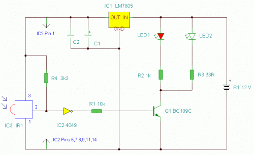
This is an enhanced infrared (IR) remote control extender circuit. It features high noise immunity, resistance to ambient and reflected light, and an extended range of approximately 7 meters from the remote control to the extender circuit. It is...
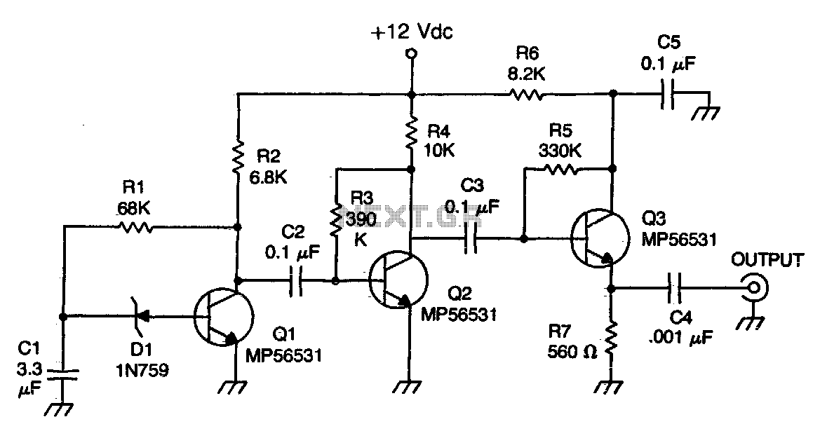
The Zener diode functions as an avalanche rectifier in reverse bias mode, connected to the input circuit of a wideband RF amplifier. The noise is amplified and subsequently applied to the cascade wideband amplifier, utilizing transistors Q2 and Q3. The...
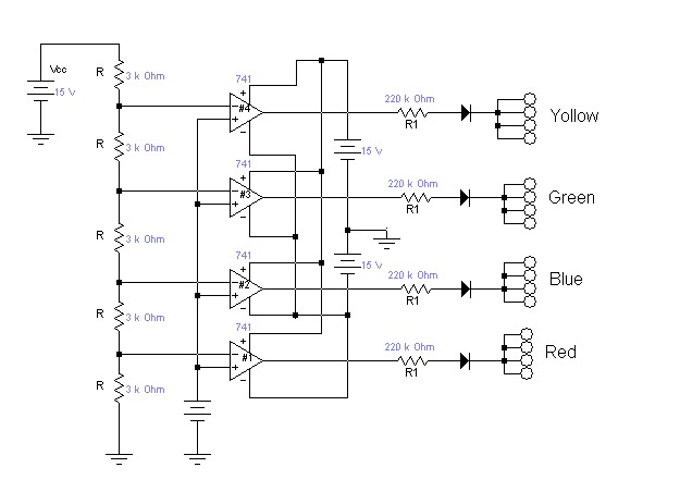
This is a color sensor circuit diagram designed to detect eight colors: green, red, blue, magenta, cyan, yellow, black, and white. It is particularly useful for robotics projects. The object whose color needs to be detected should be placed...
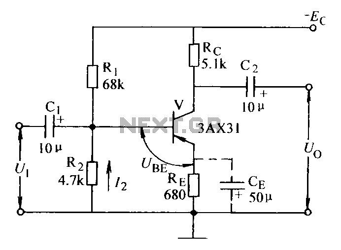
Current negative feedback voltage divider biased circuit diagram. The current negative feedback voltage divider biased circuit is a configuration commonly used in electronic amplifiers to stabilize the operating point and improve linearity. This circuit typically consists of an amplifier, a...
The circuit operates by using a clock signal to drive four D-flip-flops in the control section, which store the on/off state of each current direction for the two stepper motor coils. The flip-flops create a finite state machine (FSM)...
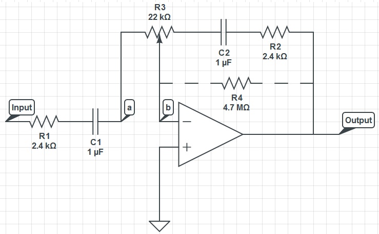
This circuit can function as a treble control circuit, with high-frequency gain occurring when resistor R3 is set to a value that makes points a and b equal (denoted as k=0). Conversely, high-frequency attenuation occurs when R3 is set...