
18W Audio Amplifier

The described unit is a high-quality audio amplifier designed for direct connection to various audio sources, such as CD players, tuners, and tape recorders, without requiring an additional preamplifier stage. This design allows for a simplified integration into audio systems while maintaining audio fidelity.
The power supply requirements specify a dual voltage of 23V, ensuring that the amplifier operates efficiently within its designated power range. Exceeding this voltage could lead to potential damage or reduced performance of the unit.
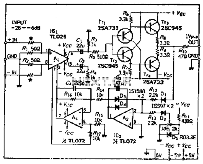
Transistors Q3 and Q4 serve as critical components in the amplifier's output stage. It is essential to mount these transistors on a heatsink to dissipate heat generated during operation, preventing thermal overload and ensuring reliable performance. The placement of diode D1 in thermal contact with transistor Q1 is significant for thermal stability, as it helps regulate the biasing of the output stage, adapting to temperature variations and maintaining consistent performance.
Quiescent current, which is the idle current flowing through the transistors when no input signal is present, is adjustable via resistor R3. The recommended quiescent current range of 20 to 30 mA is crucial for optimal operation, as it affects the amplifier's linearity and distortion characteristics. Measurement of this current should be performed using an Avo-meter in series with the emitter of Q3, ensuring accuracy in the setting process.
For further flexibility in current adjustment, an optional resistor R8 can be added to the circuit. This addition allows for finer tuning of the quiescent current, accommodating variations in component tolerances and user preferences.
Grounding is a critical aspect of the circuit design to prevent hum and ground loops, which can degrade audio quality. A single-point grounding scheme is recommended, where the ground connections of connectors J1, P1, and capacitors C2, C3, and C4 converge. This approach minimizes potential ground loop issues and enhances the overall performance of the audio amplifier. Proper attention to grounding practices will ensure a clean and noise-free audio signal, contributing to the high-quality performance of the unit.High Quality very simple unit -- No need for a preamplifier Can be directly connected to CD players, tuners and tape recorders. Don`t exceed 23 + 23V supply. Q3 and Q4 must be mounted on heatsink. D1 must be in thermal contact with Q1. Quiescent current (best measured with an Avo-meter in series with Q3 Emitter) is not critical. Adjust R3 to read a current between 20 to 30 mA with no input signal. * * * * * * To facilitate current setting add R8 (optional). * A correct grounding is very important to eliminate hum and ground loops. Connect in the same point the ground sides of J1, P1, C2, C3&C4. Co 🔗 External reference
Related Circuits
This series-feedback configuration of compounds provides a high input impedance and stable, wide-band gain video amplifier suitable for general-purpose applications. It features low capacitance and high impedance. The described video amplifier circuit utilizes a series-feedback topology to achieve high input...
The aim of this design is to reproduce a Combo amplifier of the type very common in the sixties and the seventies of the past century. It is well suited as a guitar amplifier but it will do a...
The problem with class-B amplifier design is that we start with an output stage in two halves, each with a non-linear response, which we then add together to try to give a linear response, i.e. so that a graph...
The TL494 controls a car's audio inverter power supply, which is a high-fidelity audio power supply designed for custom vehicles. It operates reliably without the need for adjustments according to the provided circuit diagram. The TL494 is a versatile integrated...
A few years ago, a decision was made to eventually replace a decades-old Nakamichi stereo system with a more mobile-friendly alternative. It became apparent that Class-D and Class-E switching amplifiers, which had been researched in the 1970s, were experiencing...
A car circuit is utilized for external voltage-controlled amplification in wideband amplifiers using the TL0216 IC. This design incorporates compression characteristics of 2dB. The input circuit consists of resistors that reduce the input level when it is between -26dB...