
Low Capacitance High Impedance Amplifier Circuit

The described video amplifier circuit utilizes a series-feedback topology to achieve high input impedance, which is essential for minimizing the loading effect on the preceding stage. This characteristic ensures that the amplifier can interface effectively with a variety of signal sources without degrading the signal integrity. The stability of the amplifier is crucial, particularly in wide-band applications where fluctuations in gain can lead to distortion or signal loss.
The circuit typically employs operational amplifiers (op-amps) or transistor-based configurations, where feedback is applied to enhance linearity and bandwidth. The low capacitance design is particularly advantageous in high-frequency applications, as it reduces the risk of signal attenuation and phase shifts that can occur due to capacitive loading.
In practical implementations, careful selection of components is necessary to maintain the desired performance. Resistors and capacitors must be chosen to ensure that the amplifier can operate effectively across the intended frequency range while maintaining low noise levels. The layout of the circuit is also critical; minimizing trace lengths and using proper grounding techniques can significantly enhance performance by reducing parasitic capacitance and inductance.
Applications for this type of amplifier include video signal processing, instrumentation, and any scenario where high-speed signal transmission is required. The versatility and reliability of this amplifier make it an essential component in modern electronic systems.This series-feedback series of compounds give a high input impedance and stable, gain wide-band video amplifier for general purpose applications. Low Capacitance, High Impedance, Amplifier Circuit,. 🔗 External reference
Related Circuits
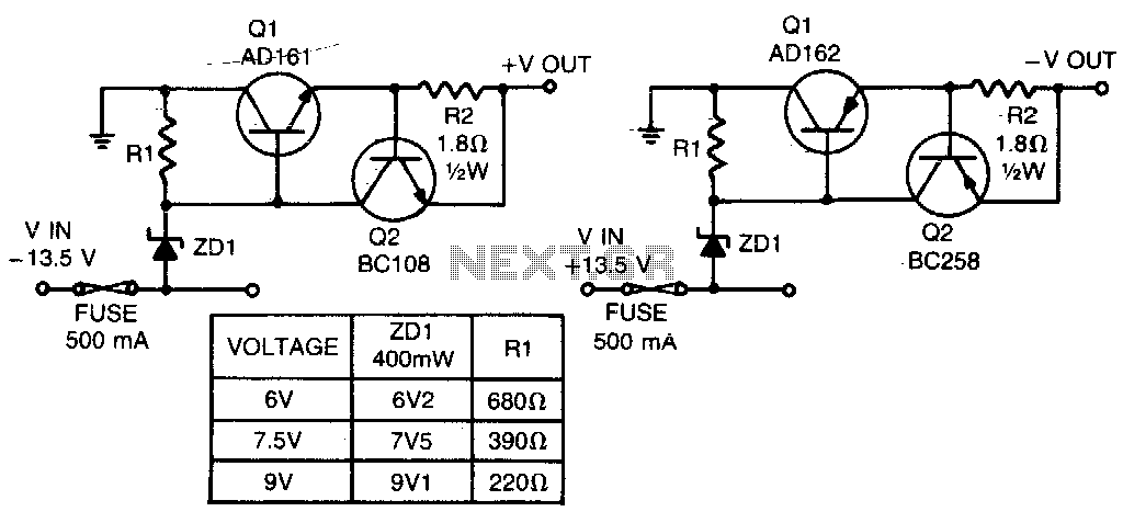
These short-circuit protected regulators provide output voltages of 6, 7, and 9 V from a nominal automobile battery supply of 13 V. They are also compatible with smoothed DC outputs from transformer/rectifier circuits. Two configurations are designed for both...
The following circuit illustrates the sensor circuit diagram for automatic room lights. This circuit is based on the CD4017 integrated circuit (IC) and features the use of two light-dependent resistors (LDRs). The automatic room light circuit utilizes the CD4017 decade...

The input capacitor is used for low-frequency cut-off, with a standard value of 0.1 µF, resulting in a cut-off frequency of approximately 16 Hz. The input capacitor plays a critical role in electronic circuits, particularly in signal processing and audio...
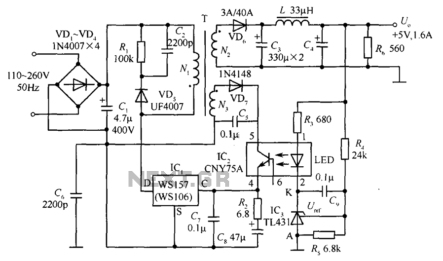
The circuit incorporates an optical coupler (CNY75A) and an adjustable precision shunt regulator (TL431). It includes current limiting resistors R3, R4, and R5 for the sampling resistor. As the output voltage (Uo) varies, the voltage across the sampling resistor...
DCF77 Preamplifier Circuit Diagram A popular project among microcontroller enthusiasts is to build a radio-controlled clock. Small receiver boards are available, equipped with a pre-adjusted ferrite antenna, that receive and demodulate the DCF77 time signal broadcast from Mainflingen in...
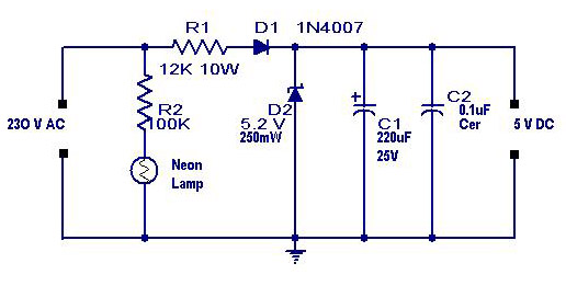
A simple transformerless power supply circuit with a diagram and schematics that provides a 5 volts DC output. This is a low-cost, low-current power supply circuit suitable for simple applications such as powering an LED. The transformerless power supply circuit...