
18W Audio Amplifier

The circuit described above can be interfaced directly with various audio devices such as CD players, tuners, and tape recorders. This indicates that the circuit is designed to handle audio signals, likely in an analog format, as these devices typically output such signals.
The circuit's ability to connect directly to these devices suggests that it has the necessary input impedance to match the output impedance of the audio devices, ensuring optimal signal transfer and minimizing signal loss or distortion. It also implies that the circuit can operate at the voltage levels output by these devices, which are typically line level voltages.
The circuit may contain components such as resistors, capacitors, and possibly operational amplifiers (op-amps) to process the audio signals. If op-amps are used, they may be configured in various ways, such as voltage followers (for impedance matching), inverting or non-inverting amplifiers (for signal amplification), or active filters (for frequency-specific amplification or attenuation).
Given the range of devices that the circuit can connect to, it likely has multiple input channels, each of which can be selected or mixed as required. These channels may be designed to handle different types of connectors, such as RCA for CD players and tuners, and 3.5mm or 1/4" TRS for tape recorders.
Lastly, the circuit may also include output stages, which could be connected to other audio processing circuits or directly to speakers. These stages would likely include additional op-amps for driving the speakers, and possibly tone control circuits for adjusting the bass, mid, and treble frequencies of the audio signal.Can be directly connected to CD players, tuners and tape recorders. 🔗 External reference
Related Circuits
The tracing of the BASH amplifier circuit for the V. 2-400 has been documented through schematics that reflect the findings. Design defects have been identified, and improvements are being implemented. Evan Shultz dedicated considerable time to tracing the circuits...
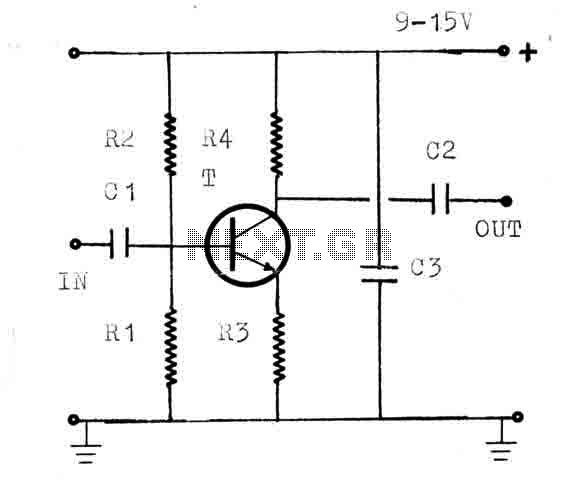
The circuit is a universal amplifier capable of amplifying any RF signal. The BF194 or BF198 transistors can be utilized. Coaxial cable should be used for connections. Additional components include: R1=22K, R2=100K, R3=18, R4=1.2K, C1=470PF, C2=470PF, C3=1NF, and T=BF194...
This is an image Schematic. No Description available. The provided input indicates the existence of a schematic image without further descriptive content. In the context of electronic schematics, such images typically represent the arrangement and interconnection of various electronic...
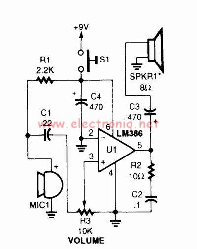
A voice amplifier can be designed using the LM386 power amplifier, which is intended for low voltage consumer applications. This simple circuit features variable gain and volume control. The gain is set internally to 20 to minimize the number...
This is a convenient and straightforward general-purpose 50-watt amplifier. The amplifier features an input for connecting devices such as radios, TVs, or stereo equipment. Additionally, it includes a phono input suitable for connecting record players, guitars, microphones, or other...
The following circuit illustrates the BUZ902DP 300 Watt Audio Power Amplifier Circuit Diagram. Features include audio frequency linearity from 20 Hz to 20 kHz. The BUZ902DP is a high-performance audio power amplifier designed to deliver up to 300 watts of...