
AM-FM-TV RF AMPLIFIER

The universal RF amplifier circuit employs either the BF194 or BF198 transistors, both of which are suitable for high-frequency applications. The circuit is designed to enhance RF signals, making it ideal for various communication tasks, including radio frequency transmission and reception.
The resistors in the circuit include R1 (22KΩ), R2 (100KΩ), R3 (18Ω), and R4 (1.2KΩ). R1 and R2 form a voltage divider that sets the biasing conditions for the transistor, ensuring it operates within its active region for optimal amplification. R3 serves as a load resistor, helping to convert the amplified current from the transistor into a voltage signal. R4 is used for emitter biasing, stabilizing the transistor's operating point against variations in temperature and transistor parameters.
Capacitors C1 (470pF), C2 (470pF), and C3 (1nF) are crucial for coupling and bypassing in the circuit. C1 and C2 are used for AC coupling, allowing the RF signals to pass while blocking any DC components, thus preventing distortion in the amplified signal. C3 serves as a bypass capacitor, helping to maintain a stable voltage across the transistor by filtering out high-frequency noise.
The use of coaxial cable for connections is essential in RF applications to minimize signal loss and interference. Coaxial cable provides a shielded environment for the signal, reducing the impact of external electromagnetic interference, which is critical for maintaining the integrity of the RF signals being amplified.
Overall, this universal amplifier circuit is versatile and can be adapted for various RF applications, making it a valuable tool in the field of electronics and communication systems. Proper assembly and layout are crucial to ensure the circuit functions as intended, with attention paid to component placement and the use of appropriate shielding techniques.The circuit is a universal amplifier that can amplify any rf signal. You can use the BF194 or the BF198. Make sure you use coaxial cable. Parts: R1=22K R2=100K R3=18 R4=1.2K C1=470PF C2=470PF C3=1NF T= BF194 OR BF198
Related Circuits
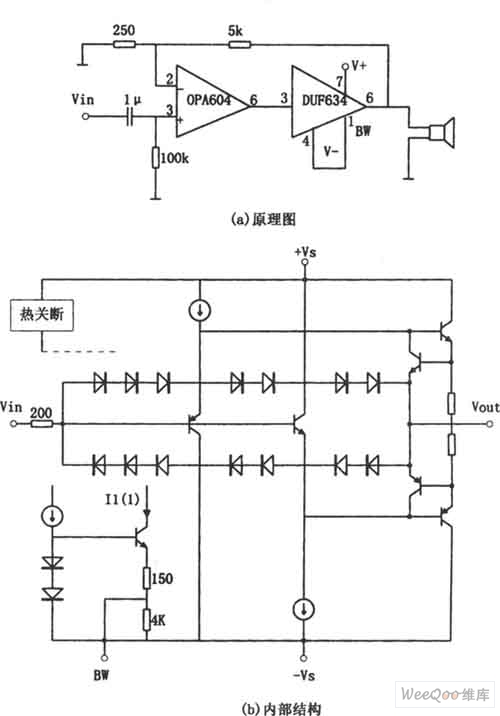
The provided image depicts a high-performance and low-power audio power amplifier circuit. The initial stage utilizes the MOSFET hi-fi operational amplifier OPA604, while the subsequent stage employs the high-speed buffer BUF634. Voltage series negative feedback is implemented between the...
This is a very simple, low-cost, Hi-Fi quality power amplifier. It can be built in five different configurations, as shown in the table, ranging from 20 W to 80 W RMS. The Hi-Fi quality power amplifier circuit is designed to...
This circuit consists of wideband RF amplifiers that utilize current-feedback components such as the THS3202. The THS3202 was selected for its fast slew rate and wide bandwidth. The amplifier voltage gain of this circuit is 20, while the stage...
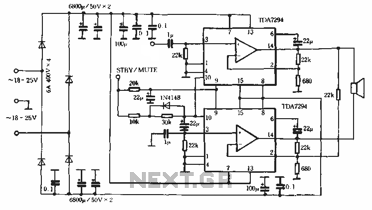
Europe's leading SGS-THOMSON STMicroelectronics recently introduced a new power integrated amplifier, the TDA7294, to the Chinese mainland market. This amplifier, characterized by a cold and hard tone, is particularly suited for Hi-Fi applications such as home theaters and active...
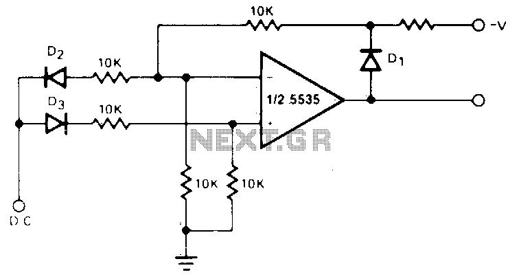
The circuit generates a positive output voltage for either polarity of input. For positive signals, it functions as a non-inverting amplifier, while for negative signals, it operates as an inverting amplifier. The accuracy is poor for input voltages under...
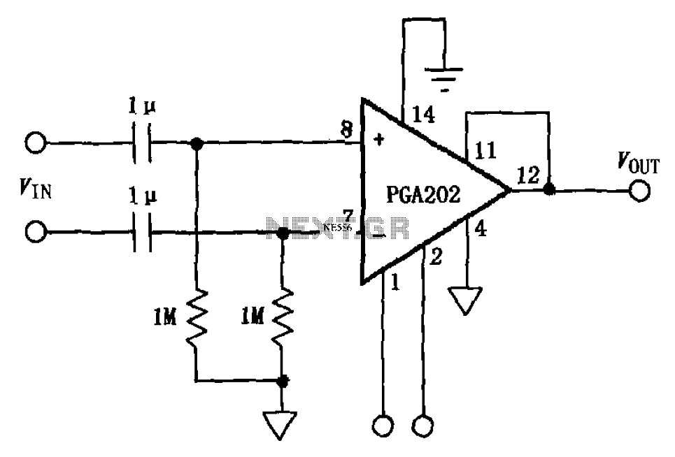
The circuit illustrated in FIG PGA202 comprises an AC-coupled differential amplifier. The input stage of PGA202 includes two 1 µF capacitors and two 1 MΩ resistors, resulting in a cutoff frequency of approximately 0.16 Hz. The Qualcomm AC coupling...