
1991 Volvo 440 Electrical Wiring Schematic Diagram

The Volvo 440, 460, and 480 series vehicles feature a comprehensive electrical installation schematic that outlines the connections and wiring configurations essential for the proper functioning of the vehicle's electrical systems. This schematic serves as a vital reference for technicians and engineers involved in the maintenance, repair, and modification of these models.
The wiring schematic typically includes detailed diagrams illustrating the layout of various electrical components, such as the battery, alternator, starter motor, ignition system, lighting, and other essential accessories. Each component is represented with specific symbols and annotations that denote their function and connection points.
The schematic is organized in a manner that allows for easy tracing of circuits, identifying potential faults, and ensuring correct wiring during installation or repairs. Color coding may be employed to differentiate between various wire types and functions, enhancing clarity and reducing the likelihood of errors during electrical work.
In addition to the primary wiring diagram, the document may also include pinout information for connectors, specifications for wire gauges, and details on fuse ratings. This information is crucial for maintaining the integrity and safety of the vehicle's electrical system, as it ensures that components operate within their designed parameters.
Overall, the electrical installation schematic for the Volvo 440, 460, and 480 series is an indispensable tool for effective vehicle maintenance, providing comprehensive guidance on the electrical architecture of these models.The following document contains information related to Volvo 440 electrical installation schematic diagram. It such the wiring schematic for Volvo 440, 460, and 480 series 🔗 External reference
Related Circuits
This circuit turns off an amplifier or any other device when a low-level audio signal fed to its input is absent for at least 15 minutes. Pressing P1 switches the device on, supplying power to any appliance connected to...

This 6V battery-operated doorbell light circuit can be connected in parallel with any existing AC 230V doorbell. When the doorbell switch is pressed, the bell sounds as usual, and the AC mains supply available across the doorbell is routed...
The circuit is a battery charging system powered by Q2, Q6, R8, and D10, which provides constant current to charge the battery. When an external power supply is present, the charging current flows through R8 and D10 to charge...
The RF oscillator utilizes inverter N2 and a 10.7 MHz ceramic filter to drive the parallel combination of inverters N4 to N6 through inverter N3. Since these inverters are connected in parallel, the output impedance is low, allowing direct...
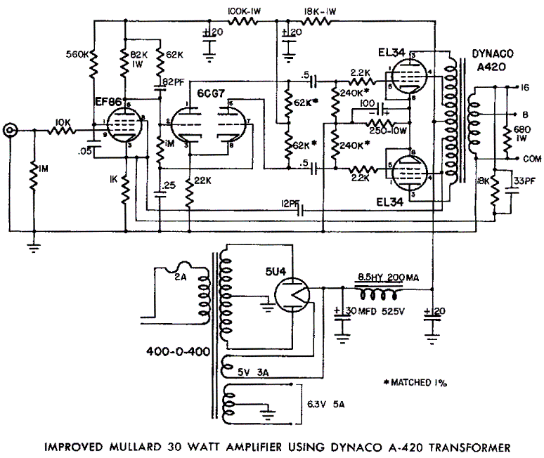
Mullard EL34 push-pull vacuum tube amplifier schematic using Dynaco A420 audio output transformers The Mullard EL34 push-pull vacuum tube amplifier is a classic audio amplification circuit that utilizes EL34 vacuum tubes in a push-pull configuration to deliver high-quality sound reproduction....
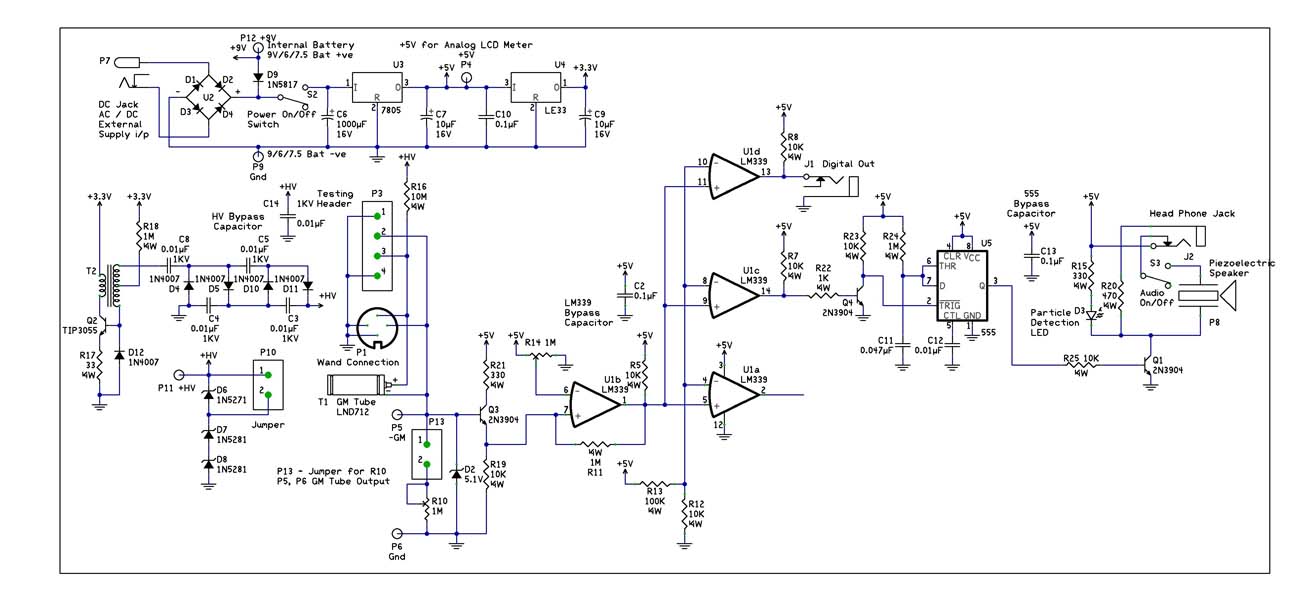
With the recent events at the Fukushima Dai-ichi nuclear power plant, it would be interesting to build a Geiger Counter and connect it to a NerdKit for interfacing with a computer. An article detailing the building process is available,...