
1995 camaro: just swapped the engine/ trans with cradle wheel well

The described 1995 Camaro's engine swap presents a complex situation requiring thorough diagnostic procedures to restore proper functionality. The initial steps involve confirming the integrity of the wiring harness and ensuring proper connections, particularly focusing on the injector circuit. The injector power supply must be verified, ensuring that the pink wire from the under-hood electrical center is delivering the necessary 12 volts to the fuel injectors.
The absence of fuel delivery, despite adequate pressure from the fuel pump, points towards a potential issue with the injector pulse. It is essential to utilize a noid light to confirm whether the PCM is sending the correct pulse-width modulated signal to the injectors. This diagnostic tool is critical since a standard voltmeter may not capture the rapid on/off signals generated by the PCM, which control fuel injection timing.
If the noid light does not illuminate, further investigation into the PCM's functioning is warranted. This includes verifying the crankshaft position sensor's output and ensuring that the camshaft position sensor is operational, as both signals are necessary for the PCM to initiate injector operation. Additionally, checking for continuity and integrity in the wiring from the injectors back to the PCM will help identify any shorts or breaks in the circuit.
Should the PCM not be responsive, it may be necessary to troubleshoot the connections related to the OBD II scanner, ensuring that the data link connector is functioning correctly, as this may provide further insight into any fault codes stored in the system. The combination of these diagnostic steps will facilitate a systematic approach to resolving the fuel delivery issue, ultimately enabling the engine to start and operate as intended.1995 camaro, just swapped the engine/ trans with cradle from a 1994. I didn`t take off any plugs from the engine and kept the computer mouted on pass. wheel well with the engine. swapped the v. a. t. s box and steering column. turns over and get spark, but no fuel. put power to the fuel pump and get 45 psi at the rail, still wont fire. have 12v at in jector fuse in the under hood fuse box. I did remove a aftermarket car alarm. all the wires in the car wiring harness were spliced into and not cut, except for one thick yellow one from the column, which is now reconnected. I have not yet checked the voltage at the fuel injectors, life has been busy. I have heard the injector plugs are under the intake runners and not very accessible. When I do test for voltage, how much is within tolorance The voltage should be battery voltage (12-13 volts).
Any codes that are set could be important, the thing you need to look at is the DATA. A code reader will not give you this. Can I put 12v to the fuel pump and injectors to get this on the road I found the power wire to the fuel pump, where would I find the wire to power the injectors (and parking/ dash lights) You must have 12 volts at the fuel injectors for the computer to operate the fuel delivery system. You can put 12 volts to bypass the faulty circuit, but be sure it is has a fuse in the circuit in case one of the injectors or circuits is shorted.
I looked around last night and couldn`t figure out which wire I should put power to for the injectors. I know the injector harness goes to the computer on the passenger wheelwell but have no idea the color codes for the wires.
The power wire for the injectors does not go to the computer. The power is switch voltage circuit. (on with ignition switch). The injector wire that goes to the computer is pulse width modulated ground signal for injector control. I am sending a schematic, look closely. The punk wire (INJECTOR FUSE) goes to the under hood electrical center. This is the wire that carries 12 volts to the fuel injectors. I`m not sure if I changed anything by testing for power, but the result is the same. When I put power to the fuel pump there is 45 psi at the fuel rail and it still doesn`t fire at all. Only with a shot of starting fluid. Ok, you have the positive you must have the injector pulse from the PCM when engine is cranking. This is a pulsating ground, when using a noid light the light should flash when plugged into an injector harness.
You must have this for the injectors to work. Get a noid lamp & plug in like I suggested. This is how you can see if the injector pulse is being processed by the PCM. This is a pulse width modulated signal, a volt meter will not show you this. At the injector connector you are looking at an off/on/off/on/off/on voltage signal that a meter will not respond quick enough to read. A "noid" lamp, you will be able to see the off/on of the light. You can get a noid lamp at Autozone, O`Rileys auto supply. or other parts suppliers. Ok, you do not have injector pulse. go back to the post I sent on 2/11 & use the schematic to trace the wiring from your injectors to the PCM.
It is necessary to have a scan tool connected to the engine to see if the computer is receiving the crank signal so it will start the injector pulse. You also need to make sure you have a cam signal-scan tool will also show this. / I picked up a Actron OBD II autoscanner. It recognizes being plugged into the data link but after "trying to connect to the vehicle computer" it says "error, check the connection and try again" Ask-a-doc Web sites: If you`ve got a quick question, you can try to get an answer from sites that say they have various specialists on hand to give quick answers.
Justanswer. com. Traffic on JustAnswer rose 14 percent. and had nearly 400, 000 page views in 30 days. inquiries related to stress, high blood pressure, drinking and heart pain jumped 33 percent. 🔗 External reference
Related Circuits
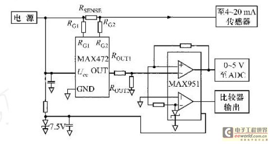
Field bus technology and intelligent instrument technology are currently two of the most rapidly evolving technologies in automation and control. In the realm of field bus technology, the CAN bus has established itself as a relatively fast communication standard...
The A3425 is a dual-output-channel bipolar switch, with each channel consisting of a complete Hall-effect sensor circuit that includes a dedicated Hall element and a separate digital output for processing speed and direction signals. The independent Hall elements (E1...
TB6556FG is a 3-phase full-wave sine-wave PWM brushless motor controller. It features sine-wave PWM control and includes a built-in triangular-wave generator with a carrier cycle defined as fosc/252 (Hz). The device also offers a built-in lead angle control function...
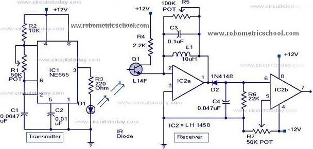
All components used in the Moving Sensor/Detector Schematic Diagram utilize the IC NE555 and the Phototransistor L14F. The primary component in this circuit is the IC NE555, along with an IR LED, the Phototransistor L14F, and the IC LM1458....
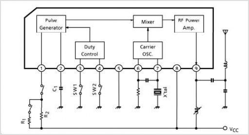
During a 50MHz SSB-QSO, my friend JE3TXU/1 (Mr. Haraguchi) mentioned that he had created a very compact 50MHz transceiver. I suggested that he should share this information in the Japanese CQ magazine. Additional details can be found in a...
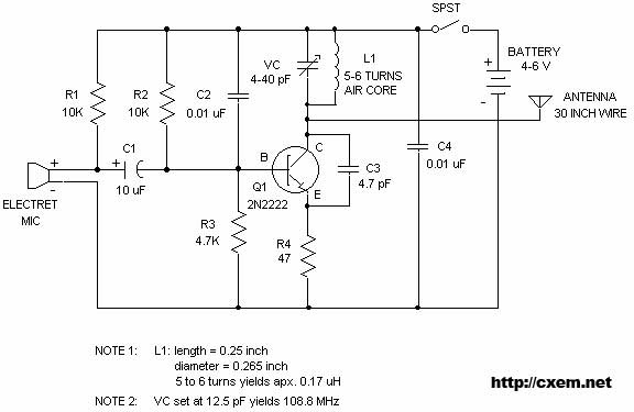
Wireless FM Transmitter. The image displays a wireless FM transmitter alongside a pocket radio and a yellow disk for size comparison. When the user speaks into the transmitter, others can hear the transmission on any FM radio. The wireless FM...