
1997 dodge dakota tailight wire diagram

To locate the wiring diagrams for the tail light and brake light systems of a 1997 Dodge Dakota extended cab sport, it is advisable to refer to the vehicle's service manual, which typically includes comprehensive wiring diagrams. These diagrams provide essential information regarding the color codes, connections, and routing of wires associated with the tail light and brake light circuits.
Additionally, online resources such as automotive forums, repair websites, and dedicated Dodge Dakota enthusiast sites may offer downloadable diagrams or user-contributed information. It is also possible to access repair databases like Alldata or Mitchell1, which provide detailed schematics and troubleshooting guides for various vehicle models.
When examining the wiring, it is crucial to understand the components involved, such as the tail light assembly, brake light switch, and any connectors that may be present. The wiring harness will typically include wires for the left and right tail lights, brake lights, and ground connections. Identifying the correct wire color and pin configuration is important for any repairs or modifications to ensure proper functionality and safety.
For hands-on assistance, consulting a professional automotive technician or an electrical specialist familiar with the Dodge Dakota may provide further guidance in troubleshooting or installing new lighting components.I just bought a 1997 dodge dakota extend cab sport how can i find a tail light wire diagram or brake light diagram ?.. 🔗 External reference
Related Circuits
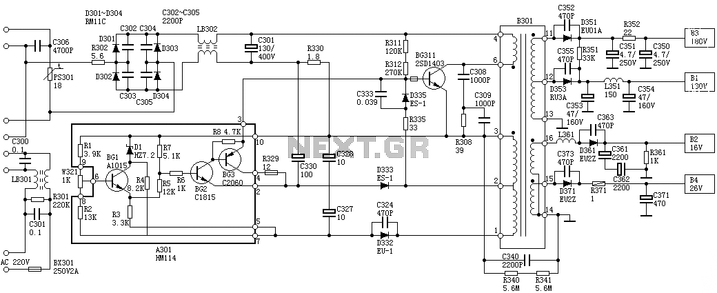
Oscillation: The positive terminal voltage of C310 is approximately 300V. The resistors R311 and R312 are connected to the switch BG311 at the B pole, while the B301 winding via the switching transformer (4) and (6) is connected to...
The RF oscillator utilizes inverter N2 and a 10.7 MHz ceramic filter to drive the parallel combination of inverters N4 to N6 through inverter N3. Since these inverters are connected in parallel, the output impedance is low, allowing direct...
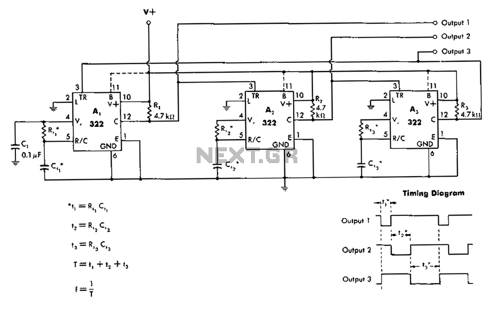
The 322 monostable multivibrator is configured in a cross-connected manner. When operating under non-steady state conditions with the oscillator Unicom, it generates a continuous timing cycle, as illustrated in the accompanying figure. T represents the total time period of...
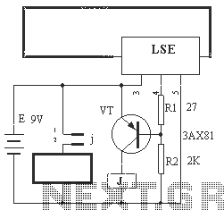
The circuit operation principle of the device illustrated in Figure 13 is as follows: When the barbed wire (Fe) remains intact, the output pin (O) of the LSE is at a high state. Consequently, the transistor (VT) remains off,...
This audio amplifier design utilizes two LM3886 chips per channel in a parallel configuration, based on the PA100 parallel amplifier detailed in National Semiconductor's application note AN1192. The amplifier can deliver approximately 50W into an 8-ohm speaker and 100W...
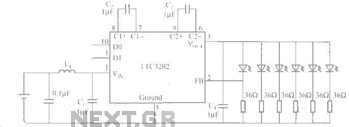
The LTC3202 is a device from Linear Technology that eliminates the need for a charge pump gated oscillator. It is designed as a charge pump for driving white LEDs powered by a lithium-ion battery. To address noise issues, the...