
Sanyo 83P switching power supply circuit diagram

The described circuit operates as a high-voltage oscillator, utilizing feedback mechanisms to regulate output voltages effectively. The oscillation begins with the activation of switch BG311, which is controlled by the positive voltage at the C310 terminal. The feedback loop involving R335, D335, and C333 plays a crucial role in saturating BG311, allowing the circuit to store energy in the transformer windings. The sawtooth waveform generated across R330 is essential for controlling the internal MOSFETs within A301, providing a mechanism for precise timing and energy transfer.
As the circuit transitions between states, the role of the diodes D351, D353, D361, and D371 is vital for ensuring that the magnetic energy stored in the transformer is efficiently converted into usable electrical energy. This conversion process is critical for producing the specified output voltages. The feedback regulation system, which samples the output voltage and adjusts the conduction times of various switches, ensures stable operation under varying load conditions. The overall design highlights the importance of feedback loops in power electronics, particularly in systems requiring high efficiency and precision in voltage regulation.Oscillation: C310 positive terminal voltage of about 300V, the R311, R312 is applied to the switch BG311 B pole, while the B301 via the switching transformer (4), (6) was added BG311 of C pole winding, the switch begins to conduct, in the B301 (2), (3) windings (2) n (3) negative positive feedback voltage, the R335, D335, C333 B pole added BG311, BG311 quickly saturated. After BG311 saturation, B301 (4), (6) winding current increases linearly, B301 stored magnetic energy.
BG311 E side current flows through R330, produces linearly increasing sawtooth voltage on the R330, the voltage through C330 to A301 (2) feet, so that the internal (2) Two foot control MOSFET, the A301's (3) feet on the B pole switch BG311 current shunt, while the negative terminal of the voltage C330 also through A301 (2), (3) was added to the foot of the B pole BG311, BG311 eventually out of saturation. BG311 Once out of saturation, the induced voltage polarity reversal of all the windings B301, B301 (2), (3) winding voltage by R335, C333 feedback, so BG311 rapidly closing.
During off BG311, D351, D353, D361, D371 are conduction, B301 magnetic energy into electrical energy is stored to be released in order to establish 180V, 130V, 16V, 26V four voltage. After BG311 off, B301 (4), (6) winding and C308, C309 and C310 produces free oscillations, after a half cycle, 300V voltage by R311, R312 to C333 charge, after a period of time, the end BG311 deadline, and enter the next cycle of oscillation.
Regulation process: Voltage winding B301 (1), (3), rectified by D332, C327 and C328 generated on the DC voltage of about 30V or so, reflecting the magnitude of the voltage magnitude of the output voltage, the voltage through A301 (7), (10) feet into the internal sampling circuit, thereby controlling BG1 current size, it controls the BG2, BG3 level of conduction, and ultimately control the switch BG311 conduction time. It controls the size of the output voltage.
Related Circuits
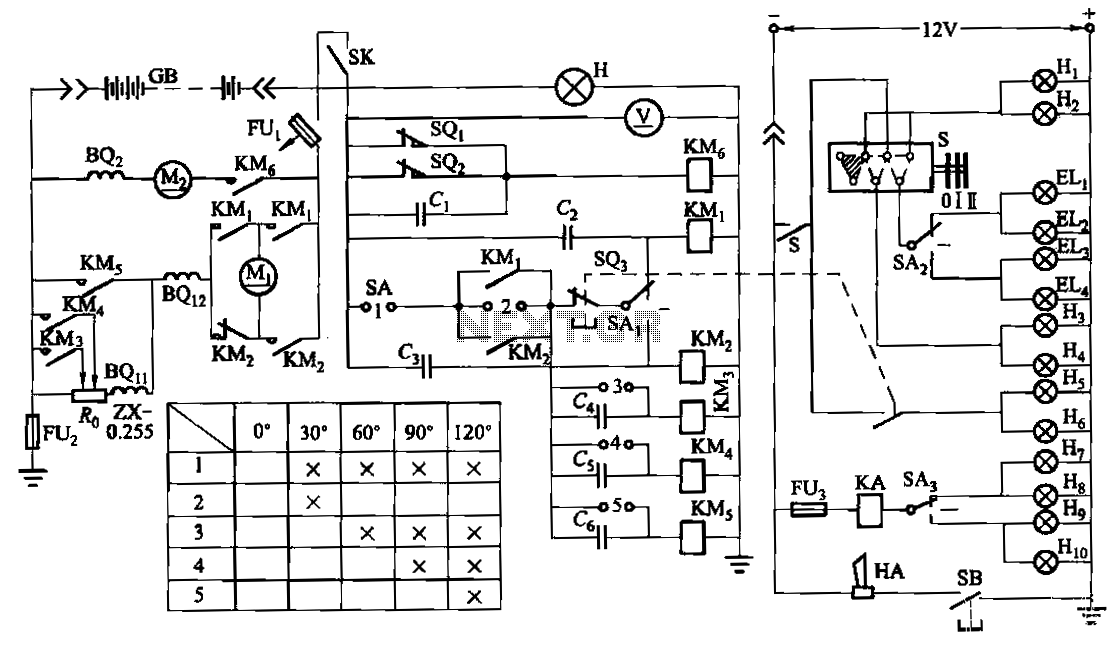
The forklift electric drive system comprises two DC series motors and associated control equipment. A 4.5 kW electric motor drives the vehicle through a mechanical transmission mechanism, enabling forward and backward movement of the forklift. A 6 kW pump...
Since I have provided the schematic for John L Linsley-Hood's Class-A amplifier, I felt that some readers may wish to experiment with the concept. Unfortunately, a very low ripple power supply is needed for all Class-A amps, and the...
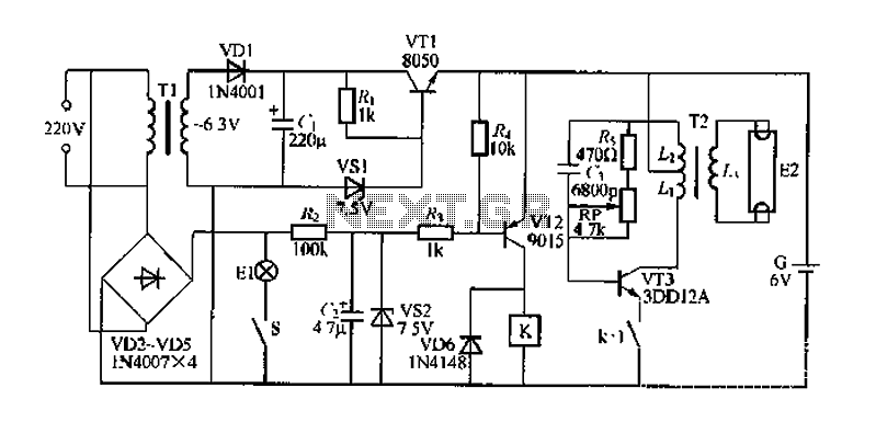
FIG. 284 illustrates a practical emergency power lighting system that activates automatically in the event of a sudden power outage. The fluorescent lights serve as emergency lighting. If the primary illumination lamp is turned off due to a power...
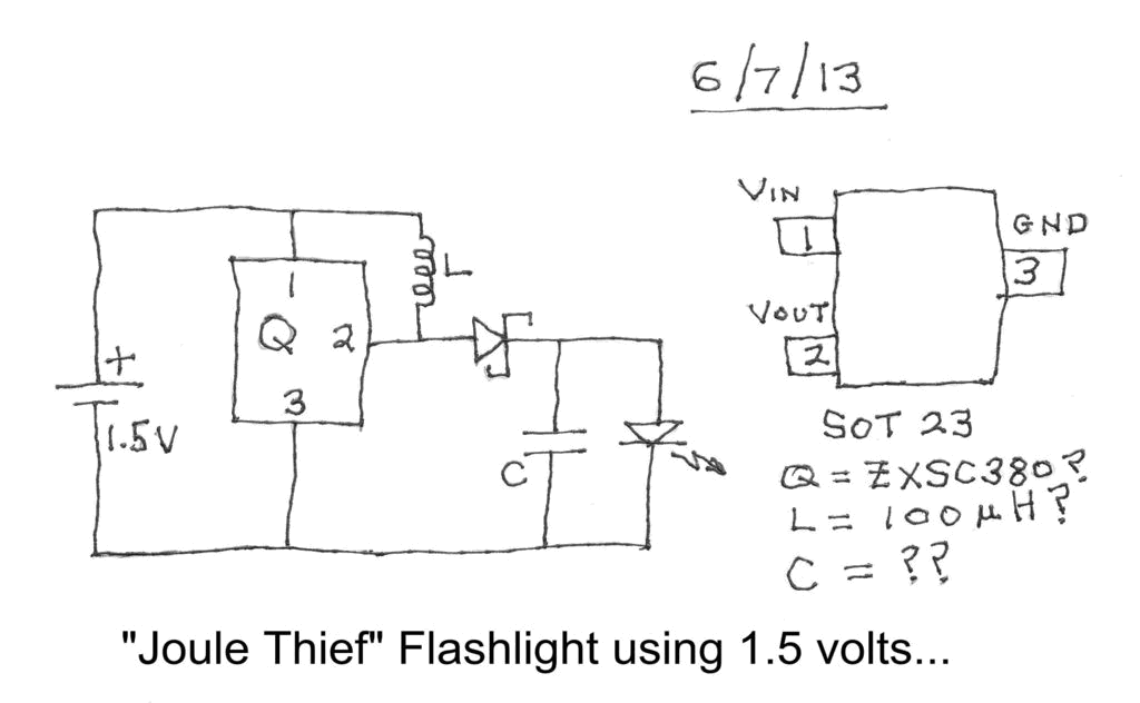
Investigating a Paradox: Recently, an energy-saving LED flashlight was observed for sale that utilized only one 1.5-volt battery. Upon purchasing this light and disassembling it, the expectation was to find a battery, bulb, switch, and a circuit board designed...

The MOC3021 is an optically isolated triac driver device. This device contains a GaAs infrared emitting diode and a light-activated silicon bilateral switch, which operates similarly to a triac. It is designed for interfacing between electronic controls and power...
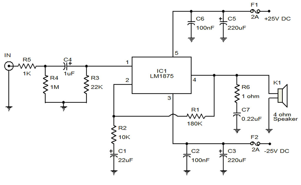
The circuit illustrates a 20-Watt audio amplifier diagram based on the LM1875 integrated circuit (IC). It is designed for use in automotive applications and provides an output power of 20 Watts. The 20-Watt audio amplifier circuit utilizing the LM1875 IC...